Vertica provides the ability to add, remove, and replace nodes on a live cluster that is actively processing queries. This ability lets you scale the database without interrupting users.
This is the multi-page printable view of this section. Click here to print.
Managing nodes
Vertica provides the ability to add, remove, and replace nodes on a live cluster that is actively processing queries.
- 1: Stop Vertica on a node
- 2: Restart Vertica on a node
- 3: Setting node type
- 4: Active standby nodes
- 4.1: Creating an active standby node
- 4.2: Replace a node with an active standby node
- 4.3: Revert active standby nodes
- 5: Large cluster
- 5.1: Planning a large cluster
- 5.2: Enabling large cluster
- 5.3: Changing the number of control nodes and realigning
- 5.4: Monitoring large clusters
- 6: Multiple databases on a cluster
- 7: Fault groups
- 7.1: About the fault group script
- 7.2: Creating a fault group input file
- 7.3: Creating fault groups
- 7.4: Monitoring fault groups
- 7.5: Dropping fault groups
- 8: Terrace routing
- 9: Elastic cluster
- 9.1: Scaling factor
- 9.2: Viewing scaling factor settings
- 9.3: Setting the scaling factor
- 9.4: Local data segmentation
- 9.5: Elastic cluster best practices
- 10: Adding nodes
- 10.1: Adding hosts to a cluster
- 10.2: Adding nodes to a database
- 10.3: Add nodes to a cluster in AWS
- 11: Removing nodes
- 11.1: Automatic eviction of unhealthy nodes
- 11.2: Lowering K-Safety to enable node removal
- 11.3: Removing nodes from a database
- 11.4: Removing hosts from a cluster
- 11.5: Remove nodes from an AWS cluster
- 12: Replacing nodes
- 12.1: Replacing a host using the same name and IP address
- 12.2: Replacing a failed node using a node with a different IP address
- 12.3: Replacing a functioning node using a different name and IP address
- 12.4: Using the administration tools to replace nodes
- 13: Rebalancing data across nodes
- 14: Redistributing configuration files to nodes
- 15: Stopping and starting nodes on MC
- 16: Upgrading your operating system on nodes in your Vertica cluster
- 17: Reconfiguring node messaging
- 17.1: re_ip command
- 17.2: Restarting a node with new host IPs
- 18: Adjusting Spread Daemon timeouts for virtual environments
1 - Stop Vertica on a node
In some cases, you need to take down a node to perform maintenance tasks, or upgrade hardware.
In some cases, you need to take down a node to perform maintenance tasks, or upgrade hardware. You can do this with one of the following:
-
Command line admintools stop_node
Important
Before removing a node from a cluster, check that the cluster has the minimum number of nodes required to comply with K-safety. If necessary, temporarily lower the database K-safety level.Administration tools
-
Run Administration Tools, select Advanced Menu, and click OK.
-
Select Stop Vertica on Host and click OK.
-
Choose the host that you want to stop and click OK.
-
Return to the Main Menu, select View Database Cluster State, and click OK. The host you previously stopped should appear DOWN.
-
You can now perform maintenance.
See Restart Vertica on a Node for details about restarting Vertica on a node.
Command line
You can use the command line tool stop_node to stop Vertica on one or more nodes. stop_node takes one or more node IP addresses as arguments. For example, the following command stops Vertica on two nodes:
$ admintools -t stop_node -s 192.0.2.1,192.0.2.2
2 - Restart Vertica on a node
After stopping a node to perform maintenance tasks such as upgrading hardware, you need to restart the node so it can reconnect with the database cluster.
After stopping a node to perform maintenance tasks such as upgrading hardware, you need to restart the node so it can reconnect with the database cluster.
-
Run Administration Tools. From the Main Menu select Restart Vertica on Host and click OK.
-
Select the database and click OK.
-
Select the host that you want to restart and click OK.
Note
This process may take a few moments. -
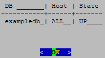
Return to the Main Menu, select View Database Cluster State, and click OK. The host you restarted now appears as UP, as shown.
3 - Setting node type
When you create a node, Vertica automatically sets its type to PERMANENT.
When you create a node, Vertica automatically sets its type to PERMANENT. This enables Vertica to use this node to store data. You can change a node's type with
ALTER NODE, to one of the following:
-
PERMANENT: (default): A node that stores data.
-
EPHEMERAL: A node that is in transition from one type to another—typically, from PERMANENT to either STANDBY or EXECUTE.
-
STANDBY: A node that is reserved to replace any node when it goes down. A standby node stores no segments or data until it is called to replace a down node. When used as a replacement node, Vertica changes its type to PERMANENT. For more information, see Active standby nodes.
-
EXECUTE: A node that is reserved for computation purposes only. An execute node contains no segments or data.
Note
STANDBY and EXECUTE node types are supported only in Enterprise Mode.4 - Active standby nodes
An active standby node exists is a node in an Enterprise Mode database that is available to replace any failed node.
An active standby node exists is a node in an Enterprise Mode database that is available to replace any failed node. Unlike permanent Vertica nodes, an standby node does not perform computations or contain data. If a permanent node fails, an active standby node can replace the failed node, after the failed node exceeds the failover time limit. After replacing the failed node, the active standby node contains the projections and performs all calculations of the node it replaced.
In this section
4.1 - Creating an active standby node
You can create active standby nodes in an Enterprise Mode database at the same time that you create the database, or later.
You can create active standby nodes in an Enterprise Mode database at the same time that you create the database, or later.
Note
When you create an active standby node, be sure to add any necessary storage locations. For more information, refer to Adding Storage Locations.Creating an active standby node in a new database
-
Create a database, including the nodes that you intend to use as active standby nodes.
-
Using vsql, connect to a node other than the node that you want to use as an active standby node.
-
Use ALTER NODE to convert the node from a permanent node to an active standby node. For example:
=> ALTER NODE v_mart_node5 STANDBY;After you issue the ALTER NODE statement, the affected node goes down and restarts as an active standby node.
Creating an active standby node in an existing database
When you create a node to be used as an active standby node, change the new node to ephemeral status as quickly as possible to prevent the cluster from moving data to it.
-
Important
Do not rebalance the database at this stage. -
Using vsql, connect to any other node.
-
Use ALTER NODE to convert the new node from a permanent node to an ephemeral node. For example:
=> ALTER NODE v_mart_node5 EPHEMERAL; -
Rebalance the cluster to remove all data from the ephemeral node.
-
Use ALTER NODE on the ephemeral node to convert it to an active standby node. For example:
=> ALTER NODE v_mart_node5 STANDBY;
4.2 - Replace a node with an active standby node
A failed node on an Enterprise Mode database can be replaced with an active standby node automatically, or manually.
A failed node on an Enterprise Mode database can be replaced with an active standby node automatically, or manually.
Important
A node must be down before it can be replaced with an active standby node. Attempts to replace a node that is up return with an error.Automatic replacement
You can configure automatic replacement of failed nodes with parameter FailoverToStandbyAfter. If enabled, this parameter specifies the length of time that an active standby node waits before taking the place of a failed node. If possible, Vertica selects a standby node from the same fault group as the failed node. Otherwise, Vertica randomly selects an available active standby node.
Manual replacement
As an administrator, you can manually replace a failed node with ALTER NODE:
-
Connect to the database with Administration Tools or vsql.
-
Replace the node with ALTER NODE...REPLACE. The REPLACE option can specify a standby node. If REPLACE is unqualified, then Vertica selects a standby node from the same fault group as the failed node, if one is available; otherwise, it randomly selects an available active standby node.
4.3 - Revert active standby nodes
When a down node in an Enterprise Mode database is ready for reactivation, you can restore it by reverting its replacement to standby status.
When a down node in an Enterprise Mode database is ready for reactivation, you can restore it by reverting its replacement to standby status. You can perform this operation on individual nodes or the entire database, with ALTER NODE and ALTER DATABASE, respectively:
-
Connect to the database with Administration Tools or via vsql.
-
Revert the standby nodes.
-
Individually with ALTER NODE:
ALTER NODE node-name RESET; -
Collectively across the database cluster with ALTER DATABASE:
ALTER DATABASE DEFAULT RESET STANDBY;
-
If a down node cannot resume operation, Vertica ignores the reset request and leaves the standby node in place.
5 - Large cluster
Vertica uses the Spread service to broadcast control messages between database nodes.
Vertica uses the Spread service to broadcast control messages between database nodes. This service can limit the growth of a Vertica database cluster. As you increase the number of cluster nodes, the load on the Spread service also increases as more participants exchange messages. This increased load can slow overall cluster performance. Also, network addressing limits the maximum number of participants in the Spread service to 120 (and often far less). In this case, you can use large cluster to overcome these Spread limitations.
When large cluster is enabled, a subset of cluster nodes, called control nodes, exchange messages using the Spread service. Other nodes in the cluster are assigned to one of these control nodes, and depend on them for cluster-wide communication. Each control node passes messages from the Spread service to its dependent nodes. When a dependent node needs to broadcast a message to other nodes in the cluster, it passes the message to its control node, which in turn sends the message out to its other dependent nodes and the Spread service.

By setting up dependencies between control nodes and other nodes, you can grow the total number of database nodes, and remain in compliance with the Spread limit of 120 nodes.
Note
Technically, when large cluster is disabled, all of the nodes in the cluster are control nodes. In this case, all nodes connect to Spread. When large cluster is enabled, some nodes become dependent on control nodes.A downside of the large cluster feature is that if a control node fails, its dependent nodes are cut off from the rest of the database cluster. These nodes cannot participate in database activities, and Vertica considers them to be down as well. When the control node recovers, it re-establishes communication between its dependent nodes and the database, so all of the nodes rejoin the cluster.
Note
The Spread service demon runs as an independent process on the control node host. It is not part of the Vertica process. If the Vertica process goes down on the node—for example, you use admintools to stop the Vertica process on the host—Spread continues to run. As long as the Spread demon runs on the control node, the node's dependents can communicate with the database cluster and participate in database activity. Normally, the control node only goes down if the node's host has an issue—or example, you shut it down, it becomes disconnected from the network, or a hardware failure occurs.Large cluster and database growth
When your database has large cluster enabled, Vertica decides whether to make a newly added node into a control or a dependent node as follows:
-
In Enterprise Mode, if the number of control nodes configured for the database cluster is greater than the current number of nodes it contains, Vertica makes the new node a control node. In Eon Mode, the number of control nodes is set at the subcluster level. If the number of control nodes set for the subcluster containing the new node is less than this setting, Vertica makes the new node a control node.
-
If the Enterprise Mode cluster or Eon Mode subcluster has reached its limit on control nodes, a new node becomes a dependent of an existing control node.
When a newly-added node is a dependent node, Vertica automatically assigns it to a control node. Which control node it chooses is guided by the database mode:
-
Enterprise Mode database: Vertica assigns the new node to the control node with the least number of dependents. If you created fault groups in your database, Vertica chooses a control node in the same fault group as the new node. This feature lets you use fault groups to organize control nodes and their dependents to reflect the physical layout of the underlying host hardware. For example, you might want dependent nodes to be in the same rack as their control nodes. Otherwise, a failure that affects the entire rack (such as a power supply failure) will not only cause nodes in the rack to go down, but also nodes in other racks whose control node is in the affected rack. See Fault groups for more information.
-
Eon Mode database: Vertica always adds new nodes to a subcluster. Vertica assigns the new node to the control node with the fewest dependent nodes in that subcluster. Every subcluster in an Eon Mode database with large cluster enabled has at least one control node. Keeping dependent nodes in the same subcluster as their control node maintains subcluster isolation.
Important
In versions of Vertica prior to 10.0.1, nodes in an Eon Mode database with large cluster enabled were not necessarily assigned a control node in their subcluster. If you have upgraded your Eon Mode database from a version of Vertica earlier than 10.0.1 and have large cluster enabled, realign the control nodes in your database. This process reassigns dependent nodes and fixes any cross-subcluster control node dependencies. See Realigning Control Nodes and Reloading Spread for more information.Spread's upper limit of 120 participants can cause errors when adding a subcluster to an Eon Mode database. If your database cluster has 120 control nodes, attempting to create a subcluster fails with an error. Every subcluster must have at least one control node. When your cluster has 120 control nodes , Vertica cannot create a control node for the new subcluster. If this error occurs, you must reduce the number of control nodes in your database cluster before adding a subcluster.
When to enable large cluster
Vertica automatically enables large cluster in two cases:
-
The database cluster contains 120 or more nodes. This is true for both Enterprise Mode and Eon Mode.
-
You create an Eon Mode subcluster (either a primary subcluster or a secondary subcluster) with an initial node count of 16 or more.
Vertica does not automatically enable large cluster if you expand an existing subcluster to 16 or more nodes by adding nodes to it.
Note
You can prevent Vertica from automatically enabling large cluster when you create a subcluster with 16 or more nodes by setting the control-set-size parameter to -1. See Creating subclusters for details.
You can choose to manually enable large cluster mode before Vertica automatically enables it. Your best practice is to enable large cluster when your database cluster size reaches a threshold:
-
For cloud-based databases, enable large cluster when the cluster contains 16 or more nodes. In a cloud environment, your database uses point-to-point network communications. Spread scales poorly in point-to-point communications mode. Enabling large cluster when the database cluster reaches 16 nodes helps limit the impact caused by Spread being in point-to-point mode.
-
For on-premises databases, enable large cluster when the cluster reaches 50 to 80 nodes. Spread scales better in an on-premises environment. However, by the time the cluster size reaches 50 to 80 nodes, Spread may begin exhibiting performance issues.
In either cloud or on-premises environments, enable large cluster if you begin to notice Spread-related performance issues. Symptoms of Spread performance issues include:
-
The load on the spread service begins to cause performance issues. Because Vertica uses Spread for cluster-wide control messages, Spread performance issues can adversely affect database performance. This is particularly true for cloud-based databases, where Spread performance problems becomes a bottleneck sooner, due to the nature of network broadcasting in the cloud infrastructure. In on-premises databases, broadcast messages are usually less of a concern because messages usually remain within the local subnet. Even so, eventually, Spread usually becomes a bottleneck before Vertica automatically enables large cluster automatically when the cluster reaches 120 nodes.
-
The compressed list of addresses in your cluster is too large to fit in a maximum transmission unit (MTU) packet (1478 bytes). The MTU packet has to contain all of the addresses for the nodes participating in the Spread service. Under ideal circumstances (when your nodes have the IP addresses 1.1.1.1, 1.1.1.2 and so on) 120 addresses can fit in this packet. This is why Vertica automatically enables large cluster if your database cluster reaches 120 nodes. In practice, the compressed list of IP addresses will reach the MTU packet size limit at 50 to 80 nodes.
5.1 - Planning a large cluster
There are two factors you should consider when planning to expand your database cluster to the point that it needs to use large cluster:.
There are two factors you should consider when planning to expand your database cluster to the point that it needs to use large cluster:
-
How many control nodes should your database cluster have?
-
How should those control nodes be distributed?
Determining the number of control nodes
When you manually enable large cluster or add enough nodes to trigger Vertica to enable it automatically, a subset of the cluster nodes become control nodes. In subclusters with fewer than 16 nodes, all nodes are control nodes. In many cases, you can set the number of control nodes to the square root of the total number of nodes in the entire Enterprise Mode cluster, or in Eon Mode subclusters with more than 16 nodes. However, this formula for calculating the number of control is not guaranteed to always meet your requirements.
When choosing the number of control nodes in a database cluster, you must balance two competing considerations:
-
If a control node fails or is shut down, all nodes that depend on it are cut off from the database. They are also down until the control node rejoins the database. You can reduce the impact of a control node failure by increasing the number of control nodes in your cluster.
-
The more control nodes in your cluster, the greater the load on the spread service. In cloud environments, increased complexity of the network environment broadcast can contribute to high latency. This latency can cause messages sent over the spread service to take longer to reach all of the nodes in the cluster.
In a cloud environment, experience has shown that 16 control nodes balances the needs of reliability and performance. In an Eon Mode database, you must have at least one control node per subcluster. Therefore, if you have more than 16 subclusters, you must have more than 16 control nodes.
In an Eon Mode database, whether on-premises or in the cloud, consider adding more control nodes to your primary subclusters than to secondary subclusters. Only nodes in primary subclusters are responsible for maintaining K-safety in an Eon Mode database. Therefore, a control node failure in a primary subcluster can have greater impact on your database than a control node failure in a secondary subcluster.
In an on-premises Enterprise Mode database, consider the physical layout of the hosts running your database when choosing the number of control nodes. If your hosts are spread across multiple server racks, you want to have enough control nodes to distribute them across the racks. Distributing the control nodes helps ensure reliability in the case of a failure that involves the entire rack (such as a power supply or network switch failure). You can configure your database so no node depends on a control node that is in a separate rack. Limiting dependency to within a rack prevents a failure that affects an entire rack from causing additional node loss outside the rack due to control node loss.
Selecting the number of control nodes based on the physical layout also lets you reduce network traffic across switches. By having dependent nodes on the same racks as their control nodes, the communications between them remain in the rack, rather that traversing a network switch.
You might need to increase the number of control nodes to evenly distribute them across your racks. For example, on-premises Enterprise Mode database has 64 total nodes, spread across three racks. The square root of the number of nodes yields 8 control nodes for this cluster. However, you cannot evenly distribute eight control nodes among the three racks. Instead, you can have 9 control nodes and evenly distribute three control nodes per rack.
Influencing control node placement
After you determine the number of nodes for your cluster, you need to determine how to distribute them among the cluster nodes. Vertica chooses which nodes become control nodes. You can influence how Vertica chooses the control nodes and which nodes become their dependents. The exact process you use depends on your database's mode:
-
Enterprise Mode on-premises database: Define fault groups to influence control node placement. Dependent nodes are always in the same fault group as their control node. You usually define fault groups that reflect the physical layout of the hosts running your database. For example, you usually define one or more fault groups for the nodes in a single rack of servers. When the fault groups reflect your physical layout, Vertica places control nodes and dependents in a way that can limit the impact of rack failures. See Fault groups for more information.
-
Eon Mode database: Use subclusters to control the placement of control nodes. Each subcluster must have at least one control node. Dependent nodes are always in the same subcluster as their control nodes. You can set the number of control nodes for each subcluster. Doing so lets you assign more control nodes to primary subclusters, where it's important to minimize the impact of a control node failure.
How Vertica chooses a default number of control nodes
Vertica can automatically choose the number of control nodes in the entire cluster (when in Enterprise Mode) or for a subcluster (when in Eon Mode). It sets a default value in these circumstances:
-
When you pass the
defaultkeyword to the--large-clusteroption of theinstall_verticascript (see Enable Large Cluster When Installing Vertica). -
Vertica automatically enables large cluster when your database cluster grows to 120 or more nodes.
-
Vertica automatically enables large cluster for an Eon Mode subcluster if you create it with more than 16 nodes. Note that Vertica does not enable large cluster on a subcluster you expand past the 16 node limit. It only enables large clusters that start out larger than 16 nodes.
The number of control nodes Vertica chooses depends on what triggered Vertica to set the value.
If you pass the --large-cluster default option to the
install_vertica script, Vertica sets the number of control nodes to the square root of the number of nodes in the initial cluster.
If your database cluster reaches 120 nodes, Vertica enables large cluster by making any newly-added nodes into dependents. The default value for the limit on the number of control nodes is 120. When you reach this limit, any newly-added nodes are added as dependents. For example, suppose you have a 115 node Enterprise Mode database cluster where you have not manually enabled large cluster. If you add 10 nodes to this cluster, Vertica adds 5 of the nodes as control nodes (bringing you up to the 120-node limit) and the other 5 nodes as dependents.
Important
You should manually enable large cluster before your database reaches 120 nodes.In an Eon Mode database, each subcluster has its own setting for the number of control nodes. Vertica only automatically sets the number of control nodes when you create a subcluster with more than 16 nodes initially. When this occurs, Vertica sets the number of control nodes for the subcluster to the square root of the number of nodes in the subcluster.
For example, suppose you add a new subcluster with 25 nodes in it. This subcluster starts with more than the 16 node limit, so Vertica sets the number of control nodes for subcluster to 5 (which is the square root of 25). Five of the nodes are added as control nodes, and the remaining 20 are added as dependents of those five nodes.
Even though each subcluster has its own setting for the number of control nodes, an Eon Mode database cluster still has the 120 node limit on the total number of control nodes that it can have.
5.2 - Enabling large cluster
Vertica enables the large cluster feature automatically when:.
Vertica enables the large cluster feature automatically when:
-
The total number of nodes in the database cluster exceeds 120.
-
You create an Eon Mode subcluster with more than 16 nodes.
In most cases, you should consider manually enabling large cluster before your cluster size reaches either of these thresholds. See Planning a large cluster for guidance on when to enable large cluster.
You can enable large cluster on a new Vertica database, or on an existing database.
Enable large cluster when installing Vertica
You can enable large cluster when installing Vertica onto a new database cluster. This option is useful if you know from the beginning that your database will benefit from large cluster.
The install_vertica script's
--large-cluster argument enables large cluster during installation. It takes a single integer value between 1 and 120 that specifies the number of control nodes to create in the new database cluster. Alternatively, this option can take the literal argument default. In this case, Vertica enables large cluster mode and sets the number of control nodes to the square root of the number nodes you provide in the
--hosts argument. For example, if --hosts specifies 25 hosts and --large-cluster is set to default, the install script creates a database cluster with 5 control nodes.
The --large-cluster argument has a slightly different effect depending on the database mode you choose when creating your database:
-
Enterprise Mode:
--large-clustersets the total number of control nodes for the entire database cluster. -
Eon Mode :
--large-clustersets the number of control nodes in the initial default subcluster. This setting has no effect on subclusters that you create later.
Note
You cannot use --large-cluster to set the number of control nodes in your initial database to be higher than the number of you pass in the --hosts argument. The installer sets the number of control nodes to whichever is the lower value: the value you pass to the --large-cluster option or the number of hosts in the --hosts option.
You can set the number of control nodes to be higher than the number of nodes currently in an existing database, with the meta-function SET_CONTROL_SET_SIZE function. You choose to set a higher number to preallocate control nodes when planning for future expansion. For details, see Changing the number of control nodes and realigning.
After the installation process completes, use the Administration tools or the [%=Vertica.MC%] to create a database. See Create an empty database for details.
If your database is on-premises and running in Enterprise Mode, you usually want to define fault groups that reflect the physical layout of your hosts. They let you define which hosts are in the same server racks, and are dependent on the same infrastructure (such power supplies and network switches). With this knowledge, Vertica can realign the control nodes to make your database better able to cope with hardware failures. See Fault groups for more information.
After creating a database, any nodes that you add are, by default, dependent nodes. You can change the number of control nodes in the database with the meta-function SET_CONTROL_SET_SIZE.
Enable large cluster in an existing database
You can manually enable large cluster in an existing database. You usually choose to enable large cluster manually before your database reaches the point where Vertica automatically enables it. See When To Enable Large Cluster for an explanation of when you should consider enabling large cluster.
Use the meta-function SET_CONTROL_SET_SIZE to enable large cluster and set the number of control nodes. You pass this function an integer value that sets the number of control nodes in the entire Enterprise Mode cluster, or in an Eon Mode subcluster.
5.3 - Changing the number of control nodes and realigning
You can change the number of control nodes in the entire database cluster in Enterprise Mode, or the number of control nodes in a subcluster in Eon Mode.
You can change the number of control nodes in the entire database cluster in Enterprise Mode, or the number of control nodes in a subcluster in Eon Mode. You may choose to change the number of control nodes in a cluster or subcluster to reduce the impact of control node loss on your database. See Planning a large cluster to learn more about when you should change the number of control nodes in your database.
You change the number of control nodes by calling the meta-function SET_CONTROL_SET_SIZE. If large cluster was not enabled before the call to SET_CONTROL_SET_SIZE, the function enables large cluster in your database. See Enabling large cluster for more information.
When you call SET_CONTROL_SET_SIZE in an Enterprise Mode database, it sets the number of control nodes in the entire database cluster. In an Eon Mode database, you must supply SET_CONTROL_SET_SIZE with the name of a subcluster in addition to the number of control nodes. The function sets the number of control nodes for that subcluster. Other subclusters in the database cluster are unaffected by this call.
Before changing the number of control nodes in an Eon Mode subcluster, verify that the subcluster is running. Changing the number of control nodes of a subcluster while it is down can cause configuration issues that prevent nodes in the subcluster from starting.
Note
You can set the number of control nodes to a value that is higher than the number of nodes currently in the cluster or subcluster. When the number of control nodes is higher than the current node count, newly-added nodes become control nodes until the number of nodes in the cluster or subcluster reaches the number control nodes you set.
You may choose to set the number of control nodes higher than the current node count to plan for future expansion. For example, suppose you have a 4-node subcluster in an Eon Mode database that you plan to expand in the future. You determine that you want limit the number of control nodes in this cluster to 8, even if you expand it beyond that size. In this case, you can choose to set the control node size for the subcluster to 8 now. As you add new nodes to the subcluster, they become control nodes until the size of the subcluster reaches 8. After that point, Vertica assigns newly-added nodes as a dependent of an existing control node in the subcluster.
Realigning control nodes and reloading spread
After you call the SET_CONTROL_SET_SIZE function, there are several additional steps you must take before the new setting takes effect.
Important
Follow these steps if you have upgraded your large-cluster enabled Eon Mode database from a version prior to 10.0.1. Earlier versions of Vertica did not restrict control node assignments to be within the same subcluster. When you realign the control nodes after an upgrade, Vertica configures each subcluster to have at least one control node, and assigns nodes to a control node in their own subcluster.-
Call the REALIGN_CONTROL_NODES function. This function tells Vertica to re-evaluate the assignment of control nodes and their dependents in your cluster or subcluster. When calling this function in an Eon Mode database, you must supply the name of the subcluster where you changed the control node settings.
-
Call the RELOAD_SPREAD function. This function updates the control node assignment information in configuration files and triggers Spread to reload.
-
Restart the nodes affected by the change in control nodes. In an Enterprise Mode database, you must restart the entire database to ensure all nodes have updated configuration information. In Eon Mode, restart the subcluster or subclusters affected by your changes. You must restart the entire Eon Mode database if you changed a critical subcluster (such as the only primary subcluster).
Note
You do not need to restart nodes if the earlier steps didn't change control node assignments. This case usually only happens when you set the number of control nodes in an Eon Mode subcluster to higher than the subcluster's current node count, and all nodes in the subcluster are already control nodes. In this case, no control nodes are added or removed, so node dependencies do not change. Because the dependencies did not change, the nodes do not need to reload the Spread configuration. -
In an Enterprise Mode database, call START_REBALANCE_CLUSTER to rebalance the cluster. This process improves your database's fault tolerance by shifting buddy projection assignments to limit the impact of a control node failure. You do not need to take this step in an Eon Mode database.
Enterprise Mode example
The following example makes 4 out of the 8 nodes in an Enterprise Mode database into control nodes. It queries the LARGE_CLUSTER_CONFIGURATION_STATUS system table which shows control node assignments for each node in the database. At the start, all nodes are their own control nodes. See Monitoring large clusters for more information the system tables associated with large cluster.
=> SELECT * FROM V_CATALOG.LARGE_CLUSTER_CONFIGURATION_STATUS;
    node_name     | spread_host_name | control_node_name
------------------+------------------+-------------------
 v_vmart_node0001 | v_vmart_node0001 | v_vmart_node0001
 v_vmart_node0002 | v_vmart_node0002 | v_vmart_node0002
 v_vmart_node0003 | v_vmart_node0003 | v_vmart_node0003
 v_vmart_node0004 | v_vmart_node0004 | v_vmart_node0004
 v_vmart_node0005 | v_vmart_node0005 | v_vmart_node0005
 v_vmart_node0006 | v_vmart_node0006 | v_vmart_node0006
 v_vmart_node0007 | v_vmart_node0007 | v_vmart_node0007
 v_vmart_node0008 | v_vmart_node0008 | v_vmart_node0008
(8 rows)

=> SELECT SET_CONTROL_SET_SIZE(4);
 SET_CONTROL_SET_SIZE
----------------------
 Control size set
(1 row)

=> SELECT REALIGN_CONTROL_NODES();
                       REALIGN_CONTROL_NODES
---------------------------------------------------------------
 The new control node assignments can be viewed in vs_nodes.
 Check vs_cluster_layout to see the proposed new layout. Reboot
 all the nodes and call rebalance_cluster now

(1 row)

=> SELECT RELOAD_SPREAD(true);
 RELOAD_SPREAD
---------------
 Reloaded
(1 row)

=> SELECT SHUTDOWN();
After restarting the database, the final step is to rebalance the cluster and query the LARGE_CLUSTER_CONFIGURATION_STATUS table to see the current control node assignments:
=> SELECT START_REBALANCE_CLUSTER();
 START_REBALANCE_CLUSTER
-------------------------
 REBALANCING
(1 row)

=> SELECT * FROM V_CATALOG.LARGE_CLUSTER_CONFIGURATION_STATUS;
    node_name     | spread_host_name | control_node_name
------------------+------------------+-------------------
 v_vmart_node0001 | v_vmart_node0001 | v_vmart_node0001
 v_vmart_node0002 | v_vmart_node0002 | v_vmart_node0002
 v_vmart_node0003 | v_vmart_node0003 | v_vmart_node0003
 v_vmart_node0004 | v_vmart_node0004 | v_vmart_node0004
 v_vmart_node0005 | v_vmart_node0001 | v_vmart_node0001
 v_vmart_node0006 | v_vmart_node0002 | v_vmart_node0002
 v_vmart_node0007 | v_vmart_node0003 | v_vmart_node0003
 v_vmart_node0008 | v_vmart_node0004 | v_vmart_node0004
(8 rows)
Eon Mode example
The following example configures 4 control nodes in an 8-node secondary subcluster named analytics. The primary subcluster is not changed. The primary differences between this example and the previous Enterprise Mode example is the need to specify a subcluster when calling SET_CONTROL_SET_SIZE, not having to restart the entire database, and not having to call START_REBALANCE_CLUSTER.
=>  SELECT * FROM V_CATALOG.LARGE_CLUSTER_CONFIGURATION_STATUS;
      node_name       |   spread_host_name   |  control_node_name
----------------------+----------------------+----------------------
 v_verticadb_node0001 | v_verticadb_node0001 | v_verticadb_node0001
 v_verticadb_node0002 | v_verticadb_node0002 | v_verticadb_node0002
 v_verticadb_node0003 | v_verticadb_node0003 | v_verticadb_node0003
 v_verticadb_node0004 | v_verticadb_node0004 | v_verticadb_node0004
 v_verticadb_node0005 | v_verticadb_node0005 | v_verticadb_node0005
 v_verticadb_node0006 | v_verticadb_node0006 | v_verticadb_node0006
 v_verticadb_node0007 | v_verticadb_node0007 | v_verticadb_node0007
 v_verticadb_node0008 | v_verticadb_node0008 | v_verticadb_node0008
 v_verticadb_node0009 | v_verticadb_node0009 | v_verticadb_node0009
 v_verticadb_node0010 | v_verticadb_node0010 | v_verticadb_node0010
 v_verticadb_node0011 | v_verticadb_node0011 | v_verticadb_node0011
(11 rows)


=> SELECT subcluster_name,node_name,is_primary,control_set_size FROM
   V_CATALOG.SUBCLUSTERS;
  subcluster_name   |      node_name       | is_primary | control_set_size
--------------------+----------------------+------------+------------------
 default_subcluster | v_verticadb_node0001 | t          |               -1
 default_subcluster | v_verticadb_node0002 | t          |               -1
 default_subcluster | v_verticadb_node0003 | t          |               -1
 analytics          | v_verticadb_node0004 | f          |               -1
 analytics          | v_verticadb_node0005 | f          |               -1
 analytics          | v_verticadb_node0006 | f          |               -1
 analytics          | v_verticadb_node0007 | f          |               -1
 analytics          | v_verticadb_node0008 | f          |               -1
 analytics          | v_verticadb_node0009 | f          |               -1
 analytics          | v_verticadb_node0010 | f          |               -1
 analytics          | v_verticadb_node0011 | f          |               -1
(11 rows)

=> SELECT SET_CONTROL_SET_SIZE('analytics',4);
 SET_CONTROL_SET_SIZE
----------------------
 Control size set
(1 row)

=> SELECT REALIGN_CONTROL_NODES('analytics');
                      REALIGN_CONTROL_NODES
-----------------------------------------------------------------------------
 The new control node assignments can be viewed in vs_nodes. Call
reload_spread(true). If the subcluster is critical, restart the database.
Otherwise, restart the subcluster

(1 row)

=> SELECT RELOAD_SPREAD(true);
 RELOAD_SPREAD
---------------
 Reloaded
(1 row)
At this point, the analytics subcluster needs to restart. You have several options to restart it. See Starting and stopping subclusters for details. This example uses the admintools command line to stop and start the subcluster.
$ admintools -t stop_subcluster -d verticadb -c analytics -p password
*** Forcing subcluster shutdown ***
Verifying subcluster 'analytics'
    Node 'v_verticadb_node0004' will shutdown
    Node 'v_verticadb_node0005' will shutdown
    Node 'v_verticadb_node0006' will shutdown
    Node 'v_verticadb_node0007' will shutdown
    Node 'v_verticadb_node0008' will shutdown
    Node 'v_verticadb_node0009' will shutdown
    Node 'v_verticadb_node0010' will shutdown
    Node 'v_verticadb_node0011' will shutdown
Shutdown subcluster command successfully sent to the database

$ admintools -t restart_subcluster -d verticadb -c analytics -p password
*** Restarting subcluster for database verticadb ***
    Restarting host [10.11.12.19] with catalog [v_verticadb_node0004_catalog]
    Restarting host [10.11.12.196] with catalog [v_verticadb_node0005_catalog]
    Restarting host [10.11.12.51] with catalog [v_verticadb_node0006_catalog]
    Restarting host [10.11.12.236] with catalog [v_verticadb_node0007_catalog]
    Restarting host [10.11.12.103] with catalog [v_verticadb_node0008_catalog]
    Restarting host [10.11.12.185] with catalog [v_verticadb_node0009_catalog]
    Restarting host [10.11.12.80] with catalog [v_verticadb_node0010_catalog]
    Restarting host [10.11.12.47] with catalog [v_verticadb_node0011_catalog]
    Issuing multi-node restart
    Starting nodes:
        v_verticadb_node0004 (10.11.12.19) [CONTROL]
        v_verticadb_node0005 (10.11.12.196) [CONTROL]
        v_verticadb_node0006 (10.11.12.51) [CONTROL]
        v_verticadb_node0007 (10.11.12.236) [CONTROL]
        v_verticadb_node0008 (10.11.12.103)
        v_verticadb_node0009 (10.11.12.185)
        v_verticadb_node0010 (10.11.12.80)
        v_verticadb_node0011 (10.11.12.47)
    Starting Vertica on all nodes. Please wait, databases with a large catalog may take a while to initialize.
    Node Status: v_verticadb_node0004: (DOWN) v_verticadb_node0005: (DOWN) v_verticadb_node0006: (DOWN)
                     v_verticadb_node0007: (DOWN) v_verticadb_node0008: (DOWN) v_verticadb_node0009: (DOWN)
                     v_verticadb_node0010: (DOWN) v_verticadb_node0011: (DOWN)
    Node Status: v_verticadb_node0004: (DOWN) v_verticadb_node0005: (DOWN) v_verticadb_node0006: (DOWN)
                     v_verticadb_node0007: (DOWN) v_verticadb_node0008: (DOWN) v_verticadb_node0009: (DOWN)
                     v_verticadb_node0010: (DOWN) v_verticadb_node0011: (DOWN)
    Node Status: v_verticadb_node0004: (INITIALIZING) v_verticadb_node0005: (INITIALIZING) v_verticadb_node0006:
                     (INITIALIZING) v_verticadb_node0007: (INITIALIZING) v_verticadb_node0008: (INITIALIZING)
                     v_verticadb_node0009: (INITIALIZING) v_verticadb_node0010: (INITIALIZING) v_verticadb_node0011: (INITIALIZING)
    Node Status: v_verticadb_node0004: (UP) v_verticadb_node0005: (UP) v_verticadb_node0006: (UP)
                     v_verticadb_node0007: (UP) v_verticadb_node0008: (UP) v_verticadb_node0009: (UP)
                     v_verticadb_node0010: (UP) v_verticadb_node0011: (UP)
Syncing catalog on verticadb with 2000 attempts.
Once the subcluster restarts, you can query the system tables to see the control node configuration:
=>  SELECT * FROM V_CATALOG.LARGE_CLUSTER_CONFIGURATION_STATUS;
      node_name       |   spread_host_name   |  control_node_name
----------------------+----------------------+----------------------
 v_verticadb_node0001 | v_verticadb_node0001 | v_verticadb_node0001
 v_verticadb_node0002 | v_verticadb_node0002 | v_verticadb_node0002
 v_verticadb_node0003 | v_verticadb_node0003 | v_verticadb_node0003
 v_verticadb_node0004 | v_verticadb_node0004 | v_verticadb_node0004
 v_verticadb_node0005 | v_verticadb_node0005 | v_verticadb_node0005
 v_verticadb_node0006 | v_verticadb_node0006 | v_verticadb_node0006
 v_verticadb_node0007 | v_verticadb_node0007 | v_verticadb_node0007
 v_verticadb_node0008 | v_verticadb_node0004 | v_verticadb_node0004
 v_verticadb_node0009 | v_verticadb_node0005 | v_verticadb_node0005
 v_verticadb_node0010 | v_verticadb_node0006 | v_verticadb_node0006
 v_verticadb_node0011 | v_verticadb_node0007 | v_verticadb_node0007
(11 rows)

=> SELECT subcluster_name,node_name,is_primary,control_set_size FROM subclusters;
  subcluster_name   |      node_name       | is_primary | control_set_size
--------------------+----------------------+------------+------------------
 default_subcluster | v_verticadb_node0001 | t          |               -1
 default_subcluster | v_verticadb_node0002 | t          |               -1
 default_subcluster | v_verticadb_node0003 | t          |               -1
 analytics          | v_verticadb_node0004 | f          |                4
 analytics          | v_verticadb_node0005 | f          |                4
 analytics          | v_verticadb_node0006 | f          |                4
 analytics          | v_verticadb_node0007 | f          |                4
 analytics          | v_verticadb_node0008 | f          |                4
 analytics          | v_verticadb_node0009 | f          |                4
 analytics          | v_verticadb_node0010 | f          |                4
 analytics          | v_verticadb_node0011 | f          |                4
(11 rows)
Disabling large cluster
To disable large cluster, call SET_CONTROL_SET_SIZE with a value of -1. This value is the default for non-large cluster databases. It tells Vertica to make all nodes into control nodes.
In an Eon Mode database, to fully disable large cluster you must to set the number of control nodes to -1 in every subcluster that has a set number of control nodes. You can see which subclusters have a set number of control nodes by querying the CONTROL_SET_SIZE column of the V_CATALOG.SUBCLUSTERS system table.
The following example resets the number of control nodes set in the previous Eon Mode example.
=> SELECT subcluster_name,node_name,is_primary,control_set_size FROM subclusters;
  subcluster_name   |      node_name       | is_primary | control_set_size
--------------------+----------------------+------------+------------------
 default_subcluster | v_verticadb_node0001 | t          |               -1
 default_subcluster | v_verticadb_node0002 | t          |               -1
 default_subcluster | v_verticadb_node0003 | t          |               -1
 analytics          | v_verticadb_node0004 | f          |                4
 analytics          | v_verticadb_node0005 | f          |                4
 analytics          | v_verticadb_node0006 | f          |                4
 analytics          | v_verticadb_node0007 | f          |                4
 analytics          | v_verticadb_node0008 | f          |                4
 analytics          | v_verticadb_node0009 | f          |                4
 analytics          | v_verticadb_node0010 | f          |                4
 analytics          | v_verticadb_node0011 | f          |                4
(11 rows)


=> SELECT SET_CONTROL_SET_SIZE('analytics',-1);
 SET_CONTROL_SET_SIZE
----------------------
 Control size set
(1 row)

=> SELECT REALIGN_CONTROL_NODES('analytics');
                       REALIGN_CONTROL_NODES
---------------------------------------------------------------------------------------
 The new control node assignments can be viewed in vs_nodes. Call reload_spread(true).
 If the subcluster is critical, restart the database. Otherwise, restart the subcluster

(1 row)

=> SELECT RELOAD_SPREAD(true);
 RELOAD_SPREAD
---------------
 Reloaded
(1 row)

-- After restarting the analytics subcluster...

=> SELECT * FROM V_CATALOG.LARGE_CLUSTER_CONFIGURATION_STATUS;
      node_name       |   spread_host_name   |  control_node_name
----------------------+----------------------+----------------------
 v_verticadb_node0001 | v_verticadb_node0001 | v_verticadb_node0001
 v_verticadb_node0002 | v_verticadb_node0002 | v_verticadb_node0002
 v_verticadb_node0003 | v_verticadb_node0003 | v_verticadb_node0003
 v_verticadb_node0004 | v_verticadb_node0004 | v_verticadb_node0004
 v_verticadb_node0005 | v_verticadb_node0005 | v_verticadb_node0005
 v_verticadb_node0006 | v_verticadb_node0006 | v_verticadb_node0006
 v_verticadb_node0007 | v_verticadb_node0007 | v_verticadb_node0007
 v_verticadb_node0008 | v_verticadb_node0008 | v_verticadb_node0008
 v_verticadb_node0009 | v_verticadb_node0009 | v_verticadb_node0009
 v_verticadb_node0010 | v_verticadb_node0010 | v_verticadb_node0010
 v_verticadb_node0011 | v_verticadb_node0011 | v_verticadb_node0011
(11 rows)

=> SELECT subcluster_name,node_name,is_primary,control_set_size FROM subclusters;
  subcluster_name   |      node_name       | is_primary | control_set_size
--------------------+----------------------+------------+------------------
 default_subcluster | v_verticadb_node0001 | t          |               -1
 default_subcluster | v_verticadb_node0002 | t          |               -1
 default_subcluster | v_verticadb_node0003 | t          |               -1
 analytics          | v_verticadb_node0004 | f          |               -1
 analytics          | v_verticadb_node0005 | f          |               -1
 analytics          | v_verticadb_node0006 | f          |               -1
 analytics          | v_verticadb_node0007 | f          |               -1
 analytics          | v_verticadb_node0008 | f          |               -1
 analytics          | v_verticadb_node0009 | f          |               -1
 analytics          | v_verticadb_node0010 | f          |               -1
 analytics          | v_verticadb_node0011 | f          |               -1
(11 rows)
5.4 - Monitoring large clusters
Monitor large cluster traits by querying the following system tables:.
Monitor large cluster traits by querying the following system tables:
-
V_CATALOG.LARGE_CLUSTER_CONFIGURATION_STATUS—Shows the current spread hosts and the control designations in the catalog so you can see if they match.
-
V_MONITOR.CRITICAL_HOSTS—Lists the hosts whose failure would cause the database to become unsafe and force a shutdown.
Tip
The CRITICAL_HOSTS view is especially useful for large cluster arrangements. For non-large clusters, query the CRITICAL_NODES table. -
In an Eon Mode database, the CONTROL_SET_SIZE column of the V_CATALOG.SUBCLUSTERS system table shows the number of control nodes set for each subcluster.
You might also want to query the following system tables:
-
V_CATALOG.FAULT_GROUPS—Shows fault groups and their hierarchy in the cluster.
-
V_CATALOG.CLUSTER_LAYOUT—Shows the relative position of the actual arrangement of the nodes participating in the database cluster and the fault groups that affect them.
6 - Multiple databases on a cluster
Vertica allows you to manage your database workloads by running multiple databases on a single cluster.
Vertica allows you to manage your database workloads by running multiple databases on a single cluster. However, databases cannot share the same node while running.
Example
If you have an 8-node cluster, with database 1 running on nodes 1, 2, 3, 4 and database 2 running on nodes 5, 6, 7, 8, you cannot create a new database in this cluster because all nodes are occupied. But if you stop database 1, you can create a database 3 using nodes 1, 2, 3, 4. Or if you stop both databases 1 and 2, you can create a database 3 using nodes 3, 4, 5, 6. In this latter case, database 1 and database 2 cannot be restarted unless you stop database 3, as they occupy the same nodes.
7 - Fault groups
You cannot create fault groups for an Eon Mode database.
Note
You cannot create fault groups for an Eon Mode database. Rather, Vertica automatically creates fault groups on a large cluster Eon database; these fault groups are configured around the control nodes and their dependents of each subcluster. These fault groups are managed internally by Vertica and are not accessible to users.Fault groups let you configure an Enterprise Mode database for your physical cluster layout. Sharing your cluster topology lets you use terrace routing to reduce the buffer requirements of large queries. It also helps to minimize the risk of correlated failures inherent in your environment, usually caused by shared resources.
Vertica automatically creates fault groups around control nodes (servers that run spread) in large cluster arrangements, placing nodes that share a control node in the same fault group. Automatic and user-defined fault groups do not include ephemeral nodes because such nodes hold no data.
Consider defining your own fault groups specific to your cluster's physical layout if you want to:
-
Use terrace routing to reduce the buffer requirements of large queries.
-
Reduce the risk of correlated failures. For example, by defining your rack layout, Vertica can better tolerate a rack failure.
-
Influence the placement of control nodes in the cluster.
Vertica supports complex, hierarchical fault groups of different shapes and sizes. The database platform provides a fault group script (DDL generator), SQL statements, system tables, and other monitoring tools.
See High availability with fault groups for an overview of fault groups with a cluster topology example.
7.1 - About the fault group script
To help you define fault groups on your cluster, Vertica provides a script named fault_group_ddl_generator.py in the /opt//scripts directory.
To help you define fault groups on your cluster, Vertica provides a script named fault_group_ddl_generator.py in the
/opt/vertica/scripts directory. This script generates the SQL statements you need to run to create fault groups.
The fault_group_ddl_generator.py script does not create fault groups for you, but you can copy the output to a file. Then, when you run the helper script, you can use \i or vsql–f commands to pass the cluster topology to Vertica.
The fault group script takes the following arguments:
-
The database name
-
The fault group input file
For example:
$ python /opt/vertica/scripts/fault_group_ddl_generator.py VMartdb fault_grp_input.out
See also
7.2 - Creating a fault group input file
Use a text editor to create a fault group input file for the targeted cluster.
Use a text editor to create a fault group input file for the targeted cluster.
The following example shows how you can create a fault group input file for a cluster that has 8 racks with 8 nodes on each rack—for a total of 64 nodes in the cluster.
-
On the first line of the file, list the parent (top-level) fault groups, delimited by spaces.
rack1 rack2 rack3 rack4 rack5 rack6 rack7 rack8 -
On the subsequent lines, list the parent fault group followed by an equals sign (=). After the equals sign, list the nodes or fault groups delimited by spaces.
<parent> = <child_1> <child_2> <child_n...>Such as:
rack1 = v_vmart_node0001 v_vmart_node0002 v_vmart_node0003 v_vmart_node0004
rack2 = v_vmart_node0005 v_vmart_node0006 v_vmart_node0007 v_vmart_node0008
rack3 = v_vmart_node0009 v_vmart_node0010 v_vmart_node0011 v_vmart_node0012
rack4 = v_vmart_node0013 v_vmart_node0014 v_vmart_node0015 v_vmart_node0016
rack5 = v_vmart_node0017 v_vmart_node0018 v_vmart_node0019 v_vmart_node0020
rack6 = v_vmart_node0021 v_vmart_node0022 v_vmart_node0023 v_vmart_node0024
rack7 = v_vmart_node0025 v_vmart_node0026 v_vmart_node0027 v_vmart_node0028
rack8 = v_vmart_node0029 v_vmart_node0030 v_vmart_node0031 v_vmart_node0032
After the first row of parent fault groups, the order in which you write the group descriptions does not matter. All fault groups that you define in this file must refer back to a parent fault group. You can indicate the parent group directly or by specifying the child of a fault group that is the child of a parent fault group.
Such as:
rack1 rack2 rack3 rack4 rack5 rack6 rack7 rack8
rack1 = v_vmart_node0001 v_vmart_node0002 v_vmart_node0003 v_vmart_node0004
rack2 = v_vmart_node0005 v_vmart_node0006 v_vmart_node0007 v_vmart_node0008
rack3 = v_vmart_node0009 v_vmart_node0010 v_vmart_node0011 v_vmart_node0012
rack4 = v_vmart_node0013 v_vmart_node0014 v_vmart_node0015 v_vmart_node0016
rack5 = v_vmart_node0017 v_vmart_node0018 v_vmart_node0019 v_vmart_node0020
rack6 = v_vmart_node0021 v_vmart_node0022 v_vmart_node0023 v_vmart_node0024
rack7 = v_vmart_node0025 v_vmart_node0026 v_vmart_node0027 v_vmart_node0028
rack8 = v_vmart_node0029 v_vmart_node0030 v_vmart_node0031 v_vmart_node0032
After you create your fault group input file, you are ready to run the fault_group_ddl_generator.py. This script generates the DDL statements you need to create fault groups in Vertica.
If your Vertica database is co-located on a Hadoop cluster, and that cluster uses more than one rack, you can use fault groups to improve performance. See Configuring rack locality.
See also
Creating fault groups7.3 - Creating fault groups
When you define fault groups, Vertica distributes data segments across the cluster.
When you define fault groups, Vertica distributes data segments across the cluster. This allows the cluster to be aware of your cluster topology so it can tolerate correlated failures inherent in your environment, such as a rack failure. For an overview, see High Availability With Fault Groups.
Important
Defining fault groups requires careful and thorough network planning, and a solid understanding of your network topology.Prerequisites
To define a fault group, you must have:
-
Superuser privileges
-
An existing database
Run the fault group script
-
As the database administrator, run the
fault_group_ddl_generator.pyscript:python /opt/vertica/scripts/fault_group_ddl_generator.py databasename fault-group-inputfile > sql-filenameFor example, the following command writes the Python script output to the SQL file
fault_group_ddl.sql.$ python /opt/vertica/scripts/fault_group_ddl_generator.py VMart fault_groups_VMart.out > fault_group_ddl.sqlAfter the script returns, you can run the SQL file, instead of multiple DDL statements individually.
Tip
Consider saving the input file so you can modify fault groups later—for example, after expanding the cluster or changing the distribution of control nodes. -
Using vsql, run the DDL statements in
fault_group_ddl.sqlor execute the commands in the file using vsql.=> \i fault_group_ddl.sql -
If large cluster is enabled, realign control nodes with REALIGN_CONTROL_NODES. Otherwise, skip this step.
=> SELECT REALIGN_CONTROL_NODES(); -
Save cluster changes to the Spread configuration file by calling RELOAD_SPREAD:
=> SELECT RELOAD_SPREAD(true); -
Use Administration tools to restart the database.
-
Save changes to the cluster's data layout by calling REBALANCE_CLUSTER:
=> SELECT REBALANCE_CLUSTER();
See also
7.4 - Monitoring fault groups
You can monitor fault groups by querying Vertica system tables or by logging in to the Management Console (MC) interface.
You can monitor fault groups by querying Vertica system tables or by logging in to the Management Console (MC) interface.
Monitor fault groups using system tables
Use the following system tables to view information about fault groups and cluster vulnerabilities, such as the nodes the cluster cannot lose without the database going down:
-
V_CATALOG.FAULT_GROUPS: View the hierarchy of all fault groups in the cluster.
-
V_CATALOG.CLUSTER_LAYOUT: Observe the arrangement of the nodes participating in the data business and the fault groups that affect them. Ephemeral nodes do not appear in the cluster layout ring because they hold no data.
Monitoring fault groups using Management Console
An MC administrator can monitor and highlight fault groups of interest by following these steps:
-
Click the running database you want to monitor and click Manage in the task bar.
-
Open the Fault Group View menu, and select the fault groups you want to view.
-
(Optional) Hide nodes that are not in the selected fault group to focus on fault groups of interest.
Nodes assigned to a fault group each have a colored bubble attached to the upper-left corner of the node icon. Each fault group has a unique color.If the number of fault groups exceeds the number of colors available, MC recycles the colors used previously.
Because Vertica supports complex, hierarchical fault groups of different shapes and sizes, MC displays multiple fault group participation as a stack of different-colored bubbles. The higher bubbles represent a lower-tiered fault group, which means that bubble is closer to the parent fault group, not the child or grandchild fault group.
For more information about fault group hierarchy, see High Availability With Fault Groups.
7.5 - Dropping fault groups
When you remove a fault group from the cluster, be aware that the drop operation removes the specified fault group and its child fault groups.
When you remove a fault group from the cluster, be aware that the drop operation removes the specified fault group and its child fault groups. Vertica places all nodes under the parent of the dropped fault group. To see the current fault group hierarchy in the cluster, query system table
FAULT_GROUPS.
Drop a fault group
Use the DROP FAULT GROUP statement to remove a fault group from the cluster. The following example shows how you can drops the group2 fault group:
=> DROP FAULT GROUP group2;
DROP FAULT GROUP
Drop all fault groups
Use the ALTER DATABASE statement to drop all fault groups, along with any child fault groups, from the specified database cluster.
The following command drops all fault groups from the current database.
=> ALTER DATABASE DEFAULT DROP ALL FAULT GROUP;
ALTER DATABASE
Add nodes back to a fault group
To add a node back to a fault group, you must manually reassign it to a new or existing fault group. To do so, use the CREATE FAULT GROUP and ALTER FAULT GROUP..ADD NODE statements.
See also
8 - Terrace routing
Before you apply terrace routing to your database, be sure you are familiar with large cluster and fault groups.
Important
Before you apply terrace routing to your database, be sure you are familiar with large cluster and fault groups.Terrace routing can significantly reduce message buffering on a large cluster database. The following sections describe how Vertica implements terrace routing on Enterprise Mode and Eon Mode databases.
Terrace routing on Enterprise Mode
Terrace routing on an Enterprise Mode database is implemented through fault groups that define a rack-based topology. In a large cluster with terrace routing disabled, nodes in a Vertica cluster form a fully connected network, where each non-dependent (control) node sends messages across the database cluster through connections with all other non-dependent nodes, both within and outside its own rack/fault group:
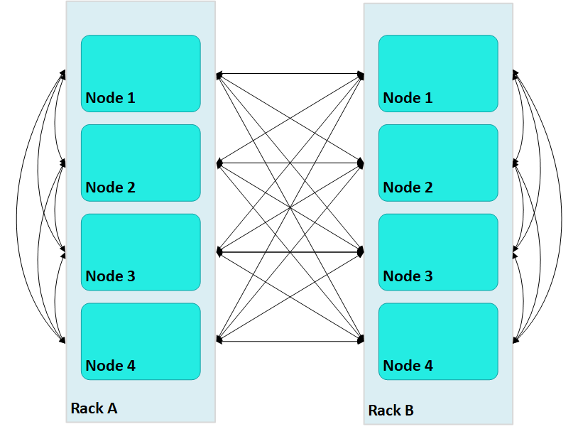
In this case, large Vertica clusters can require many connections on each node, where each connection incurs its own network buffering requirements. The total number of buffers required for each node is calculated as follows:
(numRacks * numRackNodes) - 1
In a two-rack cluster with 4 nodes per rack as shown above, this resolves to 7 buffers for each node.
With terrace routing enabled, you can considerably reduce large cluster network buffering. Each nth node in a rack/fault group is paired with the corresponding nth node of all other fault groups. For example, with terrace routing enabled, messaging in the same two-rack cluster is now implemented as follows:
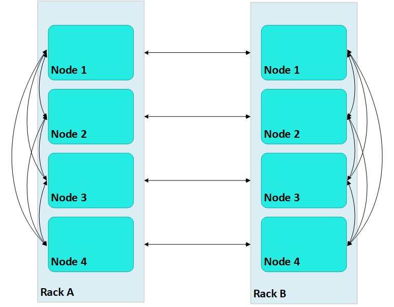
Thus, a message that originates from node 2 on rack A (A2) is sent to all other nodes on rack A; each rack A node then conveys the message to its corresponding node on rack B—A1 to B1, A2 to B2, and so on.
With terrace routing enabled, each node of a given rack avoids the overhead of maintaining message buffers to all other nodes. Instead, each node is only responsible for maintaining connections to:
-
All other nodes of the same rack (
numRackNodes- 1) -
One node on each of the other racks (
numRacks- 1)
Thus, the total number of message buffers required for each node is calculated as follows:
(numRackNodes-1) + (numRacks-1)
In a two-rack cluster with 4 nodes as shown earlier, this resolves to 4 buffers for each node.
Terrace routing trades time (intra-rack hops) for space (network message buffers). As a cluster expands with additional racks and nodes, the argument favoring this trade off becomes increasingly persuasive:
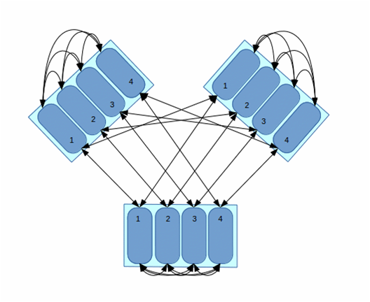
In this three-rack cluster with 4 nodes per rack, without terrace routing the number of buffers required by each node would be 11. With terrace routing, the number of buffers per node is 5. As a cluster expands with the addition of racks and nodes per rack, the disparity between buffer requirements widens. For example, given a six-rack cluster with 16 nodes per rack, without terrace routing the number of buffers required per node is 95; with terrace routing, 20.
Enabling terrace routing
Terrace routing depends on fault group definitions that describe a cluster network topology organized around racks and their member nodes. As noted earlier, when terrace routing is enabled, Vertica first distributes data within the rack/fault group; it then uses nth node-to-nth node mappings to forward this data to all other racks in the database cluster.
You enable (or disable) terrace routing for any Enterprise Mode large cluster that implements rack-based fault groups through configuration parameter TerraceRoutingFactor. To enable terrace routing, set this parameter as follows:
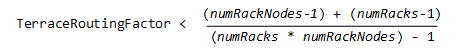
where:
-
numRackNodes: Number of nodes in a rack -
numRacks: Number of racks in the cluster
For example:
| #Racks | Nodes/rack | #Connections |
Terrace routing enabled if TerraceRoutingFactor less than: | |
|---|---|---|---|---|
| Without terrace routing | With terrace routing | |||
| 2 | 16 | 31 | 16 | 1.94 |
| 4 | 16 | 63 | 18 | 3.5 |
| 6 | 16 | 95 | 20 | 4.75 |
| 8 | 16 | 127 | 22 | 5.77 |
By default, TerraceRoutingFactor is set to 2, which generally ensures that terrace routing is enabled for any Enterprise Mode large cluster that implements rack-based fault groups. Vertica recommends enabling terrace routing for any cluster that contains 64 or more nodes, or if queries often require excessive buffer space.
To disable terrace routing, set TerraceRoutingFactor to a large integer such as 1000:
=> ALTER DATABASE DEFAULT SET TerraceRoutingFactor = 1000;
Terrace routing on Eon Mode
As in Enterprise Mode mode, terrace routing is enabled by default on an Eon Mode database, and is implemented through fault groups. However, you do not create fault groups for an Eon Mode database. Rather, Vertica automatically creates fault groups on a large cluster database; these fault groups are configured around the control nodes and their dependents of each subcluster. These fault groups are managed internally by Vertica and are not accessible to users.
9 - Elastic cluster
Elastic Cluster is an Enterprise Mode-only feature.
Note
Elastic Cluster is an Enterprise Mode-only feature. For scaling your database under Eon Mode, see Scaling your Eon Mode database.You can scale your cluster up or down to meet the needs of your database. The most common case is to add nodes to your database cluster to accommodate more data and provide better query performance. However, you can scale down your cluster if you find that it is over-provisioned, or if you need to divert hardware for other uses.
You scale your cluster by adding or removing nodes. Nodes can be added or removed without shutting down or restarting the database. After adding a node or before removing a node, Vertica begins a rebalancing process that moves data around the cluster to populate the new nodes or move data off nodes about to be removed from the database. During this process, nodes can exchange data that are not being added or removed to maintain robust intelligent K-safety. If Vertica determines that the data cannot be rebalanced in a single iteration due to lack of disk space, then the rebalance operation spans multiple iterations.
To help make data rebalancing due to cluster scaling more efficient, Vertica locally segments data storage on each node so it can be easily moved to other nodes in the cluster. When a new node is added to the cluster, existing nodes in the cluster give up some of their data segments to populate the new node. They also exchange segments to minimize the number of nodes that any one node depends upon. This strategy minimizes the number of nodes that might become critical when a node fails. When a node is removed from the cluster, its storage containers are moved to other nodes in the cluster (which also relocates data segments to minimize how many nodes might become critical when a node fails). This method of breaking data into portable segments is referred to as elastic cluster, as it facilitates enlarging or shrinking the cluster.
The alternative to elastic cluster is re-segmenting all projection data and redistributing it evenly among all database nodes any time a node is added or removed. This method requires more processing and more disk space, as it requires all data in all projections to be dumped and reloaded.
Elastic cluster scaling factor
In a new installation, each node has a scaling factor that specifies the number of local segments (see Scaling factor). Rebalance efficiently redistributes data by relocating local segments provided that, after nodes are added or removed, there are sufficient local segments in the cluster to redistribute the data evenly (determined by MAXIMUM_SKEW_PERCENT). For example, if the scaling factor = 8, and there are initially 5 nodes, then there are a total of 40 local segments cluster-wide.
If you add two additional nodes (seven nodes) Vertica relocates five local segments on two nodes, and six such segments on five nodes, resulting in roughly a 16.7 percent skew. Rebalance relocates local segments only if the resulting skew is less than the allowed threshold, as determined by MAXIMUM_SKEW_PERCENT. Otherwise, segmentation space (and hence data, if uniformly distributed over this space) is evenly distributed among the seven nodes, and new local segment boundaries are drawn for each node, such that each node again has eight local segments.
Note
By default, the scaling factor only has an effect while Vertica rebalances the database. While rebalancing, each node breaks the projection segments it contains into storage containers, which it then moves to other nodes if necessary. After rebalancing, the data is recombined into ROS containers. It is possible to have Vertica always group data into storage containers. See Local data segmentation for more information.Enabling elastic cluster
You enable elastic cluster with ENABLE_ELASTIC_CLUSTER. Query the ELASTIC_CLUSTER system table to verify that elastic cluster is enabled:
=> SELECT is_enabled FROM ELASTIC_CLUSTER;
 is_enabled
------------
 t
(1 row)
9.1 - Scaling factor
To avoid an increased number of ROS containers, do not enable local segmentation and do not change the scaling factor.
To avoid an increased number of ROS containers, do not enable local segmentation and do not change the scaling factor.
9.2 - Viewing scaling factor settings
To view the scaling factor, query the ELASTIC_CLUSTER table:.
To view the scaling factor, query the ELASTIC_CLUSTER table:
=> SELECT scaling_factor FROM ELASTIC_CLUSTER;
scaling_factor
---------------
            4
(1 row)

=> SELECT SET_SCALING_FACTOR(6);
 SET_SCALING_FACTOR
--------------------
 SET
(1 row)

=> SELECT scaling_factor FROM ELASTIC_CLUSTER;
 scaling_factor
---------------
             6
(1 row)
9.3 - Setting the scaling factor
Use the SET_SCALING_FACTOR function to change your database's scaling factor.
The scaling factor determines the number of storage containers that Vertica uses to store each projection across the database during rebalancing when local segmentation is enabled. When setting the scaling factor, follow these guidelines:
-
The number of storage containers should be greater than or equal to the number of partitions multiplied by the number of local segments:
num-storage-containers>= (num-partitions*num-local-segments) -
Set the scaling factor high enough so rebalance can transfer local segments to satisfy the skew threshold, but small enough so the number of storage containers does not result in too many ROS containers, and cause ROS pushback. The maximum number of ROS containers (by default 1024) is set by configuration parameter ContainersPerProjectionLimit.
Use the SET_SCALING_FACTOR function to change your database's scaling factor. The scaling factor can be an integer between 1 and 32.
=> SELECT SET_SCALING_FACTOR(12);
SET_SCALING_FACTOR
--------------------
 SET
(1 row)
9.4 - Local data segmentation
By default, the scaling factor only has an effect when Vertica rebalances the database.
By default, the scaling factor only has an effect when Vertica rebalances the database. During rebalancing, nodes break the projection segments they contain into storage containers which they can quickly move to other nodes.
This process is more efficient than re-segmenting the entire projection (in particular, less free disk space is required), but it still has significant overhead, since storage containers have to be separated into local segments, some of which are then transferred to other nodes. This overhead is not a problem if you rarely add or remove nodes from your database.
However, if your database is growing rapidly and is constantly busy, you may find the process of adding nodes becomes disruptive. In this case, you can enable local segmentation, which tells Vertica to always segment its data based on the scaling factor, so the data is always broken into containers that are easily moved. Having the data segmented in this way dramatically speeds up the process of adding or removing nodes, since the data is always in a state that can be quickly relocated to another node. The rebalancing process that Vertica performs after adding or removing a node just has to decide which storage containers to relocate, instead of first having to first break the data into storage containers.
Local data segmentation increases the number of storage containers stored on each node. This is not an issue unless a table contains many partitions. For example, if the table is partitioned by day and contains one or more years. If local data segmentation is enabled, then each of these table partitions is broken into multiple local storage segments, which potentially results in a huge number of files which can lead to ROS "pushback." Consider your table partitions and the effect enabling local data segmentation may have before enabling the feature.
9.4.1 - Enabling and disabling local segmentation
To enable local segmentation, use the ENABLE_LOCAL_SEGMENTS function.
To enable local segmentation, use the ENABLE_LOCAL_SEGMENTS function. To disable local segmentation, use the DISABLE_LOCAL_SEGMENTATION function:
=> SELECT ENABLE_LOCAL_SEGMENTS();
ENABLE_LOCAL_SEGMENTS
-----------------------
 ENABLED
(1 row)


=> SELECT is_local_segment_enabled FROM elastic_cluster;
 is_enabled
------------
 t
(1 row)

=> SELECT DISABLE_LOCAL_SEGMENTS();
 DISABLE_LOCAL_SEGMENTS
------------------------
 DISABLED
(1 row)

=> SELECT is_local_segment_enabled FROM ELASTIC_CLUSTER;
 is_enabled
------------
 f
(1 row)
9.5 - Elastic cluster best practices
The following are some best practices with regard to local segmentation.
The following are some best practices with regard to local segmentation.
Note
You should always perform a database backup before and after performing any of the operations discussed in this topic. You need to back up before changing any elastic cluster or local segmentation settings to guard against a hardware failure causing the rebalance process to leave the database in an unusable state. You should perform a full backup of the database after the rebalance procedure to avoid having to rebalance the database again if you need to restore from a backup.When to enable local data segmentation
Local data segmentation can significantly speed up the process of resizing your cluster. You should enable local data segmentation if:
-
your database does not contain tables with hundreds of partitions.
-
the number of nodes in the database cluster is a power of two.
-
you plan to expand or contract the size of your cluster.
Local segmentation can result in an excessive number of storage containers with tables that have hundreds of partitions, or in clusters with a non-power-of-two number of nodes. If your database has these two features, take care when enabling local segmentation.
10 - Adding nodes
There are many reasons for adding one or more nodes to an installation of Vertica:.
There are many reasons for adding one or more nodes to an installation of Vertica:
- Increase system performance. Add additional nodes due to a high query load or load latency or increase disk space without adding storage locations to existing nodes.
Note
The database response time depends on factors such as type and size of the application query, database design, data size and data types stored, available computational power, and network bandwidth. Adding nodes to a database cluster does not necessarily improve the system response time for every query, especially if the response time is already short, e.g., less then 10 seconds, or the response time is not hardware bound.-
Make the database K-safe (K-safety=1) or increase K-safety to 2. See Failure recovery for details.
-
Swap a node for maintenance. Use a spare machine to temporarily take over the activities of an existing node that needs maintenance. The node that requires maintenance is known ahead of time so that when it is temporarily removed from service, the cluster is not vulnerable to additional node failures.
-
Replace a node. Permanently add a node to remove obsolete or malfunctioning hardware.
Important
If you install Vertica on a single node without specifying the IP address or host name (or you usedlocalhost), you cannot expand the cluster. You must reinstall Vertica and specify an IP address or host name that is not localhost/127.0.0.1.
Adding nodes consists of the following general tasks:
-
Vertica strongly recommends that you back up the database before you perform this significant operation because it entails creating new projections, refreshing them, and then deleting the old projections. See Backing up and restoring the database for more information.
The process of migrating the projection design to include the additional nodes could take a while; however during this time, all user activity on the database can proceed normally, using the old projections.
-
Configure the hosts you want to add to the cluster.
See Before you Install Vertica. You will also need to edit the hosts configuration file on all of the existing nodes in the cluster to ensure they can resolve the new host.
-
Add the hosts you added to the cluster (in step 3) to the database.
Note
When you add a "host" to the database, it becomes a "node." You can add nodes to your database using either the Administration tools or the Management Console (See Monitoring with MC).
You can also add nodes using the
admintoolscommand line, which allows you to preserve the specific order of the nodes you add.
After you add nodes to the database, Vertica automatically distributes updated configuration files to the rest of the nodes in the cluster and starts the process of rebalancing data in the cluster. See Rebalancing data across nodes for details.
10.1 - Adding hosts to a cluster
After you have backed up the database and configured the hosts you want to add to the cluster, you can now add hosts to the cluster using the script.
After you have backed up the database and configured the hosts you want to add to the cluster, you can now add hosts to the cluster using the
update_vertica script.
You cannot use the MC to add hosts to a cluster in an on-premises environment. However, after the hosts are added to the cluster, the MC does allow you to add the hosts to a database as nodes.
Prerequisites and restrictions
If you installed Vertica on a single node without specifying the IP address or hostname (you used localhost), it is not possible to expand the cluster. You must reinstall Vertica and specify an IP address or hostname.
Procedure to add hosts
From one of the existing cluster hosts, run the update_vertica script with a minimum of the --add-hosts host(s) parameter (where host(s) is the hostname or IP address of the system(s) that you are adding to the cluster) and the --rpm or --deb parameter:
# /opt/vertica/sbin/update_vertica --add-hosts host(s) --rpm package
Note
See Install Vertica with the installation script for the full list of parameters. You must also provide the same options you used when originally installing the cluster.The
update_vertica ** script uses all the same options as
install_vertica and:
-
Installs the Vertica RPM on the new host.
-
Performs post-installation checks, including RPM version and N-way network connectivity checks.
-
Modifies spread to encompass the larger cluster.
-
Configures the Administration Tools to work with the larger cluster.
Important Tips:
-
Consider using
--large-clusterwith more than 50 nodes. -
A host can be specified by the hostname or IP address of the system you are adding to the cluster. However, internally Vertica stores all host addresses as IP addresses.
-
Do not use include spaces in the hostname/IP address list provided with
--add-hostsif you specified more than one host. -
If a package is specified with
--rpm/--deb, and that package is newer than the one currently installed on the existing cluster, then, Vertica first installs the new package on the existing cluster hosts before the newly-added hosts. -
Use the same command line parameters for the database administrator username, password, and directory path you used when you installed the cluster originally. Alternatively, you can create a properties file to save the parameters during install and then re-using it on subsequent install and update operations. See Installing Vertica Silently.
-
If you are installing using sudo, the database administrator user (dbadmin) must already exist on the hosts you are adding and must be configured with passwords and home directory paths identical to the existing hosts. Vertica sets up passwordless ssh from existing hosts to the new hosts, if needed.
-
If you initially used the
--point-to-pointoption to configure spread to use direct, point-to-point communication between nodes on the subnet, then use the--point-to-pointoption whenever you runinstall_verticaorupdate_vertica. Otherwise, your cluster's configuration is reverted to the default (broadcast), which may impact future databases. -
The maximum number of spread daemons supported in point-to-point communication and broadcast traffic is 80. It is possible to have more than 80 nodes by using large cluster mode, which does not install a spread daemon on each node.
Examples
--add-hosts host01 --rpm
--add-hosts 192.168.233.101
--add-hosts host02,host03
10.2 - Adding nodes to a database
After you add one or more hosts to the cluster, you can add them as nodes to the database with one of the following:.
After you add one or more hosts to the cluster, you can add them as nodes to the database with one of the following:
-
admintoolscommand line, to ensure nodes are added in a specific order -
Administration Tools
-
Management Console
Command line
With the admintools db_add_node tool, you can control the order in which nodes are added to the database cluster. It specifies the hosts of new nodes with its -s or --hosts option, which takes a comma-delimited argument list. Vertica adds new nodes in the list-specified order. For example, the following command adds three nodes:
$ admintools -t db_add_node \
      -d VMart \
      -p 'password' \
      -s 192.0.2.1,192.0.2.2,192.0.2.3
Tip
When adding nodes to an Eon Mode database, you can also specify the subcluster that the new nodes should belong to. See Adding and removing nodes from subclusters for more information.Administration tools
You add nodes to a database with the Administration Tools as follows:
-
Open the Administration Tools.
-
On the Main Menu, select View Database Cluster State to verify that the database is running. If it is not, start it.
-
From the Main Menu, select Advanced Menu and click OK.
-
In the Advanced Menu, select Cluster Management and click OK.
-
In the Cluster Management menu, select Add Host(s) and click OK.
-
Select the database to which you want to add one or more hosts, and then select OK.
A list of unused hosts is displayed.
-
Select the hosts you want to add to the database and click OK.
-
When prompted, click Yes to confirm that you want to add the hosts.
-
When prompted, enter the password for the database, and then select OK.
-
When prompted that the hosts were successfully added, select OK.
-
Vertica now automatically starts the rebalancing process to populate the new node with data. When prompted, enter the path to a temporary directory that the Database Designer can use to rebalance the data in the database and select OK.
-
Either press Enter to accept the default K-safety value, or enter a new higher value for the database and select OK.
-
Select whether to rebalance the database immediately, or later. In both cases, Vertica creates a script, which you can use to rebalance at any time.
Review the summary of the rebalancing process and select Proceed.
If you choose to automatically rebalance, the rebalance process runs. If you chose to create a script, the script is generated and saved. In either case, you are shown a success screen.
-
Select OK to complete the Add Node process.
Management Console
To add nodes to an Eon Mode database using MC, see Add nodes to a cluster in AWS using Management Console.
To add hosts to an Enterprise Mode database using MC, see Adding hosts to a cluster
10.3 - Add nodes to a cluster in AWS
This section gives an overview on how to add nodes if you are managing your cluster using admintools.
This section gives an overview on how to add nodes if you are managing your cluster using admintools. Each main step points to another topic with the complete instructions.
Step 1: before you start
Before you add nodes to a cluster, verify that you have an AWS cluster up and running and that you have:
-
Created a database.
-
Defined a database schema.
-
Loaded data.
-
Run the Database Designer.
-
Connected to your database.
Step 2: launch new instances to add to an existing cluster
Perform the procedure in Configure and launch an instance to create new instances (hosts) that you then will add to your existing cluster. Be sure to choose the same details you chose when you created the original instances (VPC, placement group, subnet, and security group).
Step 3: include new instances as cluster nodes
You need the IP addresses when you run the install_vertica script to include new instances as cluster nodes.
If you are configuring Amazon Elastic Block Store (EBS) volumes, be sure to configure the volumes on the node before you add the node to your cluster.
To add the new instances as nodes to your existing cluster:
-
Connect to the instance that is assigned to the Elastic IP. See Connect to an instance if you need more information.
-
Run the Vertica installation script to add the new instances as nodes to your cluster. Specify the internal IP addresses for your instances and your
*.pemfile name.$ sudo /opt/vertica/sbin/install_vertica --add-hosts instance-ip --dba-user-password-disabled \ --point-to-point --data-dir /vertica/data --ssh-identity ~/name-of-pem.pem
Step 4: add the nodes
After you have added the new instances to your existing cluster, add them as nodes to your cluster, as described in Adding nodes to a database.
Step 5: rebalance the database
After you add nodes to a database, always rebalance the database.
11 - Removing nodes
Although less common than adding a node, permanently removing a node is useful if the host system is obsolete or over-provisioned.
Although less common than adding a node, permanently removing a node is useful if the host system is obsolete or over-provisioned.
Important
Before removing a node from a cluster, check that the cluster has the minimum number of nodes required to comply with K-safety. If necessary, temporarily lower the database K-safety level.11.1 - Automatic eviction of unhealthy nodes
To manage the health of the nodes in your cluster, Vertica performs regular health checks by sending and receiving "heartbeats." During a health check, each node in the cluster verifies read-write access to its catalog, catalog disk, and local storage locations ('TEMP, DATA', TEMP, DATA, and DEPOT).
To manage the health of the nodes in your cluster, Vertica performs regular health checks by sending and receiving "heartbeats." During a health check, each node in the cluster verifies read-write access to its catalog, catalog disk, and local storage locations ('TEMP, DATA', TEMP, DATA, and DEPOT). Upon verification, the node sends a heartbeat. If a node fails to send a heartbeat after five intervals (fails five health checks), then the node is evicted from the cluster.
You can control the time between each health check with the DatabaseHeartBeatInterval parameter. By default, DatabaseHeartBeatInterval is set to 120, which allows five 120-second intervals to pass without a heartbeat.
The amount of time allowed before an eviction is:
TOT = DHBI * 5
where TOT is the total time (in seconds) allowed without a heartbeat before eviction, and DHBI is equal to the value of DatabaseHeartBeatInterval.
If you set the DatabaseHeartBeatInterval too low, it can cause evictions in cases of brief node health issues. Sometimes, such premature evictions result in lower availability and performance of the Vertica database.
See also
DatabaseHeartbeatInterval in General parameters
11.2 - Lowering K-Safety to enable node removal
A database with a K-safety level of 1 requires at least three nodes to operate, and a database with a K-safety level 2 requires at least 5 nodes to operate.
A database with a K-safety level of 1 requires at least three nodes to operate, and a database with a K-safety level 2 requires at least 5 nodes to operate. You can check the cluster's current K-safety level as follows:
=> SELECT current_fault_tolerance FROM system;
 current_fault_tolerance
-------------------------
                       1
(1 row)
To remove a node from a cluster with the minimum number of nodes that it requires for K-safety, first lower the K-safety level with
MARK_DESIGN_KSAFE.
Caution
Lowering the K-safety level of a database to 0 eliminates Vertica's fault tolerance features. If you must reduce K-safety to 0, first back up the database.-
Connect to the database with Administration Tools or vsql.
-
Call the function
MARK_DESIGN_KSAFE:SELECT MARK_DESIGN_KSAFE(n);where
nis the new K-safety level for the database.
11.3 - Removing nodes from a database
In an Eon Mode database, you remove nodes from the subcluster that contains them, rather than from the database.
Note
In an Eon Mode database, you remove nodes from the subcluster that contains them, rather than from the database. See Removing Nodes for more information.As long as there are enough nodes remaining to satisfy the K-Safety requirements, you can remove the node from a database. You cannot drop nodes that are critical for K-safety. See Lowering K-Safety to enable node removal.
You can remove nodes from a database using one of the following:
-
Management Console interface
-
Administration Tools
Prerequisites
Before removing a node from the database, verify that the database complies with the following requirements:
-
It is running.
-
It has been backed up.
-
The database has the minimum number of nodes required to comply with K-safety. If necessary, temporarily lower the database K-safety level.
-
All of the nodes in your database must be either up or in active standby. Vertica reports the error "All nodes must be UP or STANDBY before dropping a node" if you attempt to remove a node while a database node is down. You will get this error, even if you are trying to remove the node that is down.
Management Console
Remove nodes with Management Console from its Manage page:
Remove database nodes as follows:
-
Choose the node to remove.
-
Click Remove node in the Node List.
The following restrictions apply:
-
You can only remove nodes that belong to the database cluster.
-
You cannot remove DOWN nodes.
When you remove a node, its state changes to STANDBY. You can later add STANDBY nodes back to the database.
Administration tools
To remove unused hosts from the database using Administration Tools:
-
Open the Administration Tools. See Using the administration tools for information about accessing the Administration Tools.
-
On the Main Menu, select View Database Cluster State to verify that the database is running. If the database is not running, start it.
-
From the Main Menu, choose Advanced Menu and choose OK.
-
In the Advanced menu, choose Cluster Management and choose OK.
-
In the Cluster Management menu, choose Remove Host(s) from Database and choose OK.
-
When warned that you must redesign your database and create projections that exclude the hosts you are going to drop, choose Yes.
-
Select the database from which you want to remove the hosts and choose OK.
A list of currently active hosts appears.
-
Select the hosts you want to remove from the database and choose OK.
-
When prompted, choose OK to confirm that you want to remove the hosts.
-
When informed that the hosts were successfully removed, choose OK.
-
If you removed a host from a Large Cluster configuration, open a vsql session and run realign_control_nodes:
SELECT realign_control_nodes();For more details, see REALIGN_CONTROL_NODES.
-
If this host is not used by any other database in the cluster, you can remove the host from the cluster. See Removing hosts from a cluster.
11.4 - Removing hosts from a cluster
If a host that you removed from the database is not used by any other database, you can remove it from the cluster with.
If a host that you removed from the database is not used by any other database, you can remove it from the cluster with
update_vertica . You can leave the database running during this operation.
When you use update_vertica to reduce the size of the cluster, it also performs these tasks:
-
Modifies the spread to match the smaller cluster.
-
Configures Administration tools to work with the smaller cluster.
Note
You can use Management Console to remove hosts from a database, but you cannot remove those hosts from a cluster.From one of the Vertica cluster hosts, run
update_vertica with the –-remove-hosts switch. This switch takes an list of comma-separated hosts to remove from the cluster. You can reference hosts by their names or IP addresses. For example, you can remove hosts host01, host02, and host03 as follows:
 # /opt/vertica/sbin/update_vertica --remove-hosts host01,host02,host03 \
            --rpm /tmp/vertica-10.1.1-0.x86_64.RHEL6.rpm \
            --dba-user mydba
If --rpm specifies a new RPM, then Vertica installs it on the existing cluster hosts before proceeding.
update_vertica uses the same options as
install_vertica.For all options, see Install Vertica with the installation script.
Requirements
-
If
-remove-hosts specifies a list of multiple hosts, the list must not embed any spaces between hosts. -
Use the same command line options as in the original installation. If you used non-default values for the database administrator username, password, or directory path, provide the same settings when you remove hosts; otherwise; the procedure fails. Consider saving the original installation options in a properties file that you can reuse on subsequent installation and update operations. See Install Vertica silently.
11.5 - Remove nodes from an AWS cluster
Use the following procedures to remove instances/nodes from an AWS cluster.
Use the following procedures to remove instances/nodes from an AWS cluster.
To avoid data loss, Vertica strongly recommends that you back up your database before removing a node. For details, see Backing up and restoring the database.
Remove hosts from the database
Before you remove hosts from the database, verify that you have:
-
Backed up the database.
-
Lowered the K-safety of the database.
Note
Do not stop the database.To remove a host from the database:
-
While logged on as dbadmin, launch Administration Tools.
$ /opt/vertica/bin/admintools -
From the Main Menu, select Advanced Menu.
-
From Advanced Menu, select Cluster Management. ClickOK.
-
From Cluster Management, select Remove Host(s). Click OK.
-
From Select Database, choose the database from which you plan to remove hosts. Click OK.
-
Select the host(s) to remove. Click OK.
-
Click Yes to confirm removal of the hosts.
Note
Enter a password if necessary. Leave blank if there is no password. -
Click OK. The system displays a message telling you that the hosts have been removed. Automatic rebalancing also occurs.
-
Click OK to confirm. Administration Tools brings you back to the Cluster Management menu.
Remove nodes from the cluster
To remove nodes from a cluster, run the update_vertica script and specify:
-
The option
--remove-hosts, followed by the IP addresses of the nodes you are removing. -
The option
--ssh-identity, followed by the location and name of your*pemfile. -
The option
--dba-user-password-disabled.
The following example removes one node from the cluster:
$ sudo /opt/vertica/sbin/update_vertica  --remove-hosts 10.0.11.165  --point-to-point  \
  --ssh-identity ~/name-of-pem.pem --dba-user-password-disabled
Stop the AWS instances
After you have removed one or more nodes from your cluster, to save costs associated with running instances, you can choose to stop the AWS instances that were previously part of your cluster.
To stop an instance in AWS:
-
On AWS, navigate to your Instances page.
-
Right-click the instance, and choose Stop.
This step is optional because, after you have removed the node from your Vertica cluster, Vertica no longer sees the node as part of the cluster, even though it is still running within AWS.
12 - Replacing nodes
If you have a database, you can replace nodes, as necessary, without bringing the system down.
If you have a K-Safe database, you can replace nodes, as necessary, without bringing the system down. For example, you might want to replace an existing node if you:
-
Need to repair an existing host system that no longer functions and restore it to the cluster
-
Want to exchange an existing host system for another more powerful system
Note
Vertica does not support replacing a node on a K-safe=0 database. Use the procedures to add and remove nodes instead.The process you use to replace a node depends on whether you are replacing the node with:
-
A host that uses the same name and IP address
-
A host that uses a different name and IP address
-
An active standby node
Prerequisites
-
Configure the replacement hosts for Vertica. See Before you Install Vertica.
-
Read the Important Tipssections under Adding hosts to a cluster and Removing hosts from a cluster.
-
Ensure that the database administrator user exists on the new host and is configured identically to the existing hosts. Vertica will setup passwordless ssh as needed.
-
Ensure that directories for Catalog Path, Data Path, and any storage locations are added to the database when you create it and/or are mounted correctly on the new host and have read and write access permissions for the database administrator user. Also ensure that there is sufficient disk space.
-
Follow the best practice procedure below for introducing the failed hardware back into the cluster to avoid spurious full-node rebuilds.
Best practice for restoring failed hardware
Following this procedure will prevent Vertica from misdiagnosing missing disk or bad mounts as data corruptions, which would result in a time-consuming, full-node recovery.
If a server fails due to hardware issues, for example a bad disk or a failed controller, upon repairing the hardware:
-
Reboot the machine into runlevel 1, which is a root and console-only mode.
Runlevel 1 prevents network connectivity and keeps Vertica from attempting to reconnect to the cluster.
-
In runlevel 1, validate that the hardware has been repaired, the controllers are online, and any RAID recover is able to proceed.
Note
You do not need to initialize RAID recover in runlevel 1; simply validate that it can recover. -
Once the hardware is confirmed consistent, only then reboot to runlevel 3 or higher.
At this point, the network activates, and Vertica rejoins the cluster and automatically recovers any missing data. Note that, on a single-node database, if any files that were associated with a projection have been deleted or corrupted, Vertica will delete all files associated with that projection, which could result in data loss.
12.1 - Replacing a host using the same name and IP address
If a host of an existing Vertica database is removed you can replace it while the database is running.
If a host of an existing Vertica database is removed you can replace it while the database is running.
Note
Remember a host in Vertica consists of the hardware and operating system on which Vertica software resides, as well as the same network configurations.You can replace the host with a new host that has the following same characteristics as the old host:
-
Name
-
IP address
-
Operating system
-
The OS administrator user
-
Directory location
Replacing the host while your database is running prevents system downtime. Before replacing a host, backup your database. See Backing up and restoring the database for more information.
Replace a host using the same characteristics as follows:
-
Run install_vertica from a functioning host using the --rpm or --deb parameter:
$ /opt/vertica/sbin/install_vertica --rpm rpm_packageFor more information see Install Vertica using the command line.
-
Use Administration Tools from an existing node to restart the new host. See Restart Vertica on a node.
The node automatically joins the database and recovers its data by querying the other nodes in the database. It then transitions to an UP state.
12.2 - Replacing a failed node using a node with a different IP address
Replacing a failed node with a host system that has a different IP address from the original consists of the following steps:.
Replacing a failed node with a host system that has a different IP address from the original consists of the following steps:
-
Vertica recommends that you back up the database before you perform this significant operation because it entails creating new projections, deleting old projections, and reloading data.
-
Add the new host to the cluster. See Adding hosts to a cluster.
-
If Vertica is still running in the node being replaced, then use the Administration Tools to Stop Vertica on Host on the host being replaced.
-
Use the Administration Tools to replace the original host with the new host. If you are using more than one database, replace the original host in all the databases in which it is used. See Replacing Hosts.
-
Use the procedure in Distributing Configuration Files to the New Host to transfer metadata to the new host.
-
Use the Administration Tools to restart Vertica on the host. On the Main Menu, select Restart Vertica on Host, and click OK. See Starting the database for more information.
Once you have completed this process, the replacement node automatically recovers the data that was stored in the original node by querying other nodes within the database.
12.3 - Replacing a functioning node using a different name and IP address
Replacing a node with a host system that has a different IP address and host name from the original consists of the following general steps:.
Replacing a node with a host system that has a different IP address and host name from the original consists of the following general steps:
-
Vertica recommends that you back up the database before you perform this significant operation because it entails creating new projections, deleting old projections, and reloading data.
-
Add the replacement hosts to the cluster.
At this point, both the original host that you want to remove and the new replacement host are members of the cluster.
-
Use the Administration Tools to Stop Vertica on Host on the host being replaced.
-
Use the Administration Tools to replace the original host with the new host. If you are using more than one database, replace the original host in all the databases in which it is used. See Replacing Hosts.
-
Restart Vertica on the host.
Once you have completed this process, the replacement node automatically recovers the data that was stored in the original node by querying the other nodes within the database. It then transitions to an UP state.
Note
If you do not remove the original host from the cluster and you attempt to restart the database, the host is not invited to join the database because its node address does not match the new address stored in the database catalog. Therefore, it remains in the INITIALIZING state.12.4 - Using the administration tools to replace nodes
If you are replacing a node with a host that uses a different name and IP address, use the Administration Tools to replace the original host with the new host.
If you are replacing a node with a host that uses a different name and IP address, use the Administration Tools to replace the original host with the new host. Alternatively, you can use the Management Console to replace a node.
Replace the original host with a new host using the administration tools
To replace the original host with a new host using the Administration Tools:
-
Back up the database. See Backing up and restoring the database.
-
From a node that is up, and is not going to be replaced, open the Administration tools.
-
On the Main Menu, select View Database Cluster State to verify that the database is running. If it’s not running, use the Start Database command on the Main Menu to restart it.
-
On the Main Menu, select Advanced Menu.
-
In the Advanced Menu, select Stop Vertica on Host.
-
Select the host you want to replace, and then click OK to stop the node.
-
When prompted if you want to stop the host, select Yes.
-
In the Advanced Menu, select Cluster Management, and then click OK.
-
In the Cluster Management menu, select Replace Host, and then click OK.
-
Select the database that contains the host you want to replace, and then click OK.
A list of all the hosts that are currently being used displays.
-
Select the host you want to replace, and then click OK.
-
Select the host you want to use as the replacement, and then click OK.
-
When prompted, enter the password for the database, and then click OK.
-
When prompted, click Yes to confirm that you want to replace the host.
-
When prompted that the host was successfully replaced, click OK.
-
In the Main Menu, select View Database Cluster State to verify that all the hosts are running. You might need to start Vertica on the host you just replaced. Use Restart Vertica on Host.
The node enters a RECOVERING state.
Caution
If you are using a K-Safe database, keep in mind that the recovering node counts as one node down even though it might not yet contain a complete copy of the data. This means that if you have a database in which K safety=1, the current fault tolerance for your database is at a critical level. If you lose one more node, the database shuts down. Be sure that you do not stop any other nodes.13 - Rebalancing data across nodes
Vertica can rebalance your database when you add or remove nodes.
Vertica can rebalance your database when you add or remove nodes. As a superuser, you can manually trigger a rebalance with Administration Tools, SQL functions, or the Management Console.
A rebalance operation can take some time, depending on the cluster size, and the number of projections and the amount of data they contain. You should allow the process to complete uninterrupted. If you must cancel the operation, call
CANCEL_REBALANCE_CLUSTER.
Why rebalance?
Rebalancing is useful or even necessary after you perform one of the following operations:
-
Change the size of the cluster by adding or removing nodes.
-
Mark one or more nodes as ephemeral in preparation of removing them from the cluster.
-
Change the scaling factor of an elastic cluster, which determines the number of storage containers used to store a projection across the database.
-
Set the control node size or realign control nodes on a large cluster layout.
-
Specify more than 120 nodes in your initial Vertica cluster configuration.
-
Modify a fault group by adding or removing nodes.
General rebalancing tasks
When you rebalance a database cluster, Vertica performs the following tasks for all projections, segmented and unsegmented alike:
-
Distributes data based on:
-
User-defined fault groups, if specified
-
Large cluster automatic fault groups
-
-
Ignores node-specific distribution specifications in projection definitions. Node rebalancing always distributes data across all nodes.
-
When rebalancing is complete, sets the Ancient History Mark the greatest allowable epoch (now).
Vertica rebalances segmented and unsegmented projections differently, as described below.
Rebalancing segmented projections
For each segmented projection, Vertica performs the following tasks:
-
Copies and renames projection buddies and distributes them evenly across all nodes. The renamed projections share the same base name.
-
Refreshes the new projections.
-
Drops the original projections.
Rebalancing unsegmented projections
For each unsegmented projection, Vertica performs the following tasks:
If adding nodes:
-
Creates projection buddies on them.
-
Maps the new projections to their shared name in the database catalog.
If dropping nodes: drops the projection buddies from them.
K-safety and rebalancing
Until rebalancing completes, Vertica operates with the existing K-safe value. After rebalancing completes, Vertica operates with the K-safe value specified during the rebalance operation. The new K-safe value must be equal to or higher than current K-safety. Vertica does not support downgrading K-safety and returns a warning if you try to reduce it from its current value. For more information, see Lowering K-Safety to enable node removal.
Rebalancing failure and projections
If a failure occurs while rebalancing the database, you can rebalance again. If the cause of the failure has been resolved, the rebalance operation continues from where it failed. However, a failed data rebalance can result in projections becoming out of date.
To locate out-of-date projections, query the system table
PROJECTIONS as follows:
=> SELECT projection_name, anchor_table_name, is_up_to_date FROM projections
   WHERE is_up_to_date = false;
To remove out-of-date projections, use
DROP PROJECTION.
Temporary tables
Node rebalancing has no effect on projections of temporary tables.
For Detailed Information About Rebalancing
See the Knowledge Base articles:
13.1 - Rebalancing data using the administration tools UI
To rebalance the data in your database:.
To rebalance the data in your database:
-
Open the Administration Tools. (See Using the administration tools.)
-
On the Main Menu, select View Database Cluster State to verify that the database is running. If it is not, start it.
-
From the Main Menu, select Advanced Menu and click OK.
-
In the Advanced Menu, select Cluster Management and click OK.
-
In the Cluster Management menu, select Re-balance Data and click OK.
-
Select the database you want to rebalance, and then select OK.
-
Enter the directory for the Database Designer outputs (for example
/tmp)and click OK. -
Accept the proposed K-safety value or provide a new value. Valid values are 0 to 2.
-
Review the message and click Proceed to begin rebalancing data.
The Database Designer modifies existing projections to rebalance data across all database nodes with the K-safety you provided. A script to rebalance data, which you can run manually at a later time, is also generated and resides in the path you specified; for example
/tmp/extend_catalog_rebalance.sql.Important
Rebalancing data can take some time, depending on the number of projections and the amount of data they contain. Vertica recommends that you allow the process to complete. If you must cancel the operation, use Ctrl+C.The terminal window notifies you when the rebalancing operation is complete.
-
Press Enter to return to the Administration Tools.
13.2 - Rebalancing data using SQL functions
Vertica has three SQL functions for starting and stopping a cluster rebalance.
Vertica has three SQL functions for starting and stopping a cluster rebalance. You can call these functions from a script that runs during off-peak hours, rather than manually trigger a rebalance through Administration Tools.
-
REBALANCE_CLUSTERrebalances the database cluster synchronously as a session foreground task. -
START_REBALANCE_CLUSTERasynchronously rebalances the database cluster as a background task. -
CANCEL_REBALANCE_CLUSTERstops any rebalance task that is currently in progress or is waiting to execute.
14 - Redistributing configuration files to nodes
The add and remove node processes automatically redistribute the Vertica configuration files.
The add and remove node processes automatically redistribute the Vertica configuration files. You rarely need to redistribute the configuration files to help resolve configuration issues.
To distribute configuration files to a host:
-
Log on to a host that contains these files and start Administration Tools.
-
On the Administration Tools Main Menu, select Configuration Menu and click OK.
-
On the Configuration Menu, select Distribute Config Files and click OK.
-
Select Database Configuration.
-
Select the database where you want to distribute the files and click OK.
Vertica configuration files are distributed to all other database hosts. If the files already existed on a host, they are overwritten.
-
On the Configuration Menu, select Distribute Config Files and click OK.
-
Select SSL Keys.
Certifications and keys are distributed to all other database hosts. If they already existed on a host, they are overwritten.
-
On the Configuration Menu, select Distribute Config Files and click OK.
Select AdminTools Meta-Data.
Administration Tools metadata is distributed to every host in the cluster.
Note
To distribute the configuration file admintools.conf via the command line or scripts, use the admintools option distribute_config_files:
$ admintools -t distribute_config_files
15 - Stopping and starting nodes on MC
You can start and stop one or more database nodes through the Manage page by clicking a specific node to select it and then clicking the Start or Stop button in the Node List.
You can start and stop one or more database nodes through the Manage page by clicking a specific node to select it and then clicking the Start or Stop button in the Node List.
Note
The Stop and Start buttons in the toolbar start and stop the database, not individual nodes.On the Databases and Clusters page, you must click a database first to select it. To stop or start a node on that database, click the View button. You'll be directed to the Overview page. Click Manage in the applet panel at the bottom of the page and you'll be directed to the database node view.
The Start and Stop database buttons are always active, but the node Start and Stop buttons are active only when one or more nodes of the same status are selected; for example, all nodes are UP or DOWN.
After you click a Start or Stop button, Management Console updates the status and message icons for the nodes or databases you are starting or stopping.
16 - Upgrading your operating system on nodes in your Vertica cluster
If you need to upgrade the operating system on the nodes in your Vertica cluster, check with the documentation for your Linux distribution to make sure they support the particular upgrade you are planning.
If you need to upgrade the operating system on the nodes in your Vertica cluster, check with the documentation for your Linux distribution to make sure they support the particular upgrade you are planning.
For example, the following articles provide information about upgrading Red Hat:
-
How do I upgrade from Red Hat Enterprise Linux 6 to Red Hat Enterprise Linux 7?
-
Does Red Hat support upgrades between major versions of Red Hat Enterprise Linux?
After you confirm that you can perform the upgrade, follow the steps at Best Practices for Upgrading the Operating System on Nodes in a Vertica Cluster.
17 - Reconfiguring node messaging
Sometimes, nodes of an existing, operational Vertica database cluster require new IP addresses.
Sometimes, nodes of an existing, operational Vertica database cluster require new IP addresses. Cluster nodes might also need to change their messaging protocols—for example, from broadcast to point-to-point. The admintools re_ip utility performs both tasks.
Note
You cannot change from one address family—IPv4 or IPv6—to another. For example, if hosts in the database cluster are identified by IPv4 network addresses, you can only change host addresses to another set of IPv4 addresses.Changing IP addresses
You can use re_ip to perform two tasks:
In both cases, re_ip requires a mapping file that identifies the current node IP addresses, which are stored in admintools.conf. You can get these addresses in two ways:
-
Use the admintools utility
list_allnodes:$ admintools -t list_allnodes Node | Host | State | Version | DB -----------------+---------------+-------+----------------+----------- v_vmart_node0001 | 192.0.2.254 | UP | vertica-12.0.1 | VMart v_vmart_node0002 | 192.0.2.255 | UP | vertica-12.0.1 | VMart v_vmart_node0003 | 192.0.2.256 | UP | vertica-12.0.1 | VMartTip
list_allnodescan help you identify issues that you might have to access Vertica. For example, if hosts are not communicating with each other, theVersioncolumn displays Unavailable. -
Print the content of
admintools.conf:$ cat /opt/vertica/config/admintools.conf ... [Cluster] hosts = 192.0.2.254, 192.0.2.255, 192.0.2.256 [Nodes] node0001 = 192.0.2.254/home/dbadmin,/home/dbadmin node0002 = 192.0.2.255/home/dbadmin,/home/dbadmin node0003 = 192.0.2.256/home/dbadmin,/home/dbadmin ...
Update node IP addresses
You can update IP addresses with re_ip as described below. re_ip automatically backs up admintools.conf so you can recover the original settings if necessary.
-
Create a mapping file with lines in the following format:
oldIPaddress newIPaddress[, controlAddress, controlBroadcast]
...
For example:
192.0.2.254 198.51.100.255, 198.51.100.255, 203.0.113.255 192.0.2.255 198.51.100.256, 198.51.100.256, 203.0.113.255 192.0.2.256 198.51.100.257, 198.51.100.257, 203.0.113.255controlAddressandcontrolBroadcastare optional. If omitted:-
controlAddressdefaults tonewIPaddress. -
controlBroadcastdefaults to the host ofnewIPaddress’s broadcast IP address.
-
-
Stop the database.
-
Run
re_ipto map old IP addresses to new IP addresses:$ admintools -t re_ip -f mapfilere_ipissues warnings for the following mapping file errors:-
IP addresses are incorrectly formatted.
-
Duplicate IP addresses, whether old or new.
If
re_ipfinds no syntax errors, it performs the following tasks:-
Remaps the IP addresses as listed in the mapping file.
-
If the
-ioption is omitted, asks to confirm updates to the database. -
Updates required local configuration files with the new IP addresses.
-
Distributes the updated configuration files to the hosts using new IP addresses.
For example:
Parsing mapfile... New settings for Host 192.0.2.254 are: address: 198.51.100.255 New settings for Host 192.0.2.255 are: address: 198.51.100.256 New settings for Host 192.0.2.254 are: address: 198.51.100.257 The following databases would be affected by this tool: Vmart Checking DB status ... Enter "yes" to write new settings or "no" to exit > yes Backing up local admintools.conf ... Writing new settings to local admintools.conf ... Writing new settings to the catalogs of database Vmart ... The change was applied to all nodes. Success. Change committed on a quorum of nodes. Initiating admintools.conf distribution ... Success. Local admintools.conf sent to all hosts in the cluster. -
-
Restart the database.
re_ip and export IP address
By default, a node's IP address and its export IP address are identical. For example:
=> SELECT node_name, node_address, export_address FROM nodes;
    node_name      | node_address    | export_address
------------------------------------------------------
v_VMartDB_node0001 | 192.168.100.101 | 192.168.100.101
v_VMartDB_node0002 | 192.168.100.102 | 192.168.100.101
v_VMartDB_node0003 | 192.168.100.103 | 192.168.100.101
v_VMartDB_node0004 | 192.168.100.104 | 192.168.100.101
(4 rows)
The export address is the IP address of the node on the network. This address provides access to other DBMS systems, and enables you to import and export data across the network.
If node IP and export IP addresses are the same, then running re_ip changes both to the new address. Conversely, if you manually change the export address, subsequent re_ip operations leave your export address changes untouched.
Change node control and broadcast addresses
You can map IP addresses for the database only, by using the re_ip option -O (or --db-only). Database-only operations are useful for error recovery. The node names and IP addresses that are specified in the mapping file must be the same as the node information in admintools.conf. In this case, admintools.conf is not updated. Vertica updates only spread.conf and the catalog with the changes.
You can also use re_ip to change the node control and broadcast addresses. In this case the mapping file must contain the control messaging IP address and associated broadcast address. This task allows nodes on the same host to have different data and control addresses.
-
Create a mapping file with lines in the following format:
nodeName nodeIPaddress, controlAddress, controlBroadcast
    ...
Tip
Query the system table NODES for node names.For example:
vertica_node001 192.0.2.254, 203.0.113.255, 203.0.113.258 vertica_node002 192.0.2.255, 203.0.113.256, 203.0.113.258 vertica_node003 192.0.2.256, 203.0.113.257, 203.0.113.258 -
Stop the database.
-
Run the following command to map the new IP addresses:
$ admintools -t re_ip -f mapfile -O -d dbname -
Restart the database.
Changing node messaging protocols
You can use re_ip to reconfigure spread messaging between Vertica nodes. re_ip configures node messaging to broadcast or point-to-point (unicast) messaging with these options:
-
-U,--broadcast(default) -
-T,--point-to-point
Both options support up to 80 spread daemons. You can exceed the 80-node limit by using large cluster mode, which does not install a spread daemon on each node.
For example, to set the database cluster messaging protocol to point-to-point:
$ admintools -t re_ip -d dbname -T
To set the messaging protocol to broadcast:
$ admintools -t re_ip -d dbname -U
Setting re_ip timeout
You can configure how long re_ip executes a given task before it times out, by editing the setting of prepare_timeout_sec in admintools.conf. By default, this parameter is set to 7200 (seconds).
17.1 - re_ip command
Updates database cluster node IP addresses and reconfigures spread messaging between nodes.
Updates database cluster node IP addresses and reconfigures spread messaging between nodes.
Syntax
admintools -t re_ip { -h
   | -f mapfile [-O -d dbname]
   | -d dbname { -T | U }
} [-i]
Options
| Option | Description |
|---|---|
-h | --help |
Displays online help. |
-f mapfile | --file=mapfile |
Name of the mapping text file used to map old addresses to new ones. |
-O | --dba-only |
Used for error recovery, updates and replaces data on the database cluster catalog and control messaging system. If the mapping file fails, Vertica automatically recreates it when you re-run the command. For details, see Change Node Control and Broadcast Addresses. This option updates only one database at a time, so it requires the |
-T | --point-to-point |
Sets control messaging to the point-to-point (unicast) protocol. Vertica can change the messaging protocol on only one database at a time, so you must specify the target database with the Use point-to-point if nodes are not located on the same subnet. Point-to-point supports up to 80 spread daemons. You can exceed the 80-node limit by using large cluster mode, which does not install a spread daemon on each node. |
-U | --broadcast |
Sets control messaging to the broadcast protocol, the default setting. Vertica can change the messaging protocol on only one database at a time, so you must specify the target database with the Broadcast supports up to 80 spread daemons. You can exceed the 80-node limit by using large cluster mode, which does not install a spread daemon on each node. |
-d dbname | --database=dbname |
Database name, required with the following
|
-i | --noprompts |
System does not prompt to validate new settings before executing the re_ip operation. Prompting is on by default. |
17.2 - Restarting a node with new host IPs
For information about remapping node IP addresses on a non-Kubernetes database, see Mapping New IP Addresses.
Kubernetes only
Note
For information about remapping node IP addresses on a non-Kubernetes database, see Reconfiguring node messaging.The node IP addresses of an Eon Mode database on Kubernetes must occasionally be updated—for example, a pod fails, or is added to the cluster or rescheduled. When this happens, you must update the Vertica catalog with the new IP addresses of affected nodes and restart the node.
Note
You cannot switch an existing database cluster from one address family to another. For example, you cannot change the IP addresses of the nodes in your database from IPv4 to IPv6.Vertica's restart_node tool addresses these requirements with its --new-host-ips option, which lets you change the node IP addresses of an Eon Mode database running on Kubernetes, and restart the updated nodes. Unlike remapping node IP addresses on other (non-Kubernetes) databases, you can perform this task on individual nodes in a running database:
admintools -t restart_node \
  {-d db-name |--database=db-name} [-p password | --password=password] \
  {{-s nodes-list | --hosts=nodes-list} --new-host-ips=ip-address-list}
-
nodes-listis a comma-delimited list of nodes to restart. All nodes in the list must be down, otherwise admintools returns an error. -
ip-address-listis a comma-delimited list of new IP addresses or host names to assign to the specified nodes.Note
Because a host name resolves to an IP address, Vertica recommends that you use the IP address to eliminate unneeded complexity.
The following requirements apply to nodes-list and ip-address-list:
-
The number of node hosts and IP addresses or host names must be the same.
-
The lists must not include any embedded spaces.
For example, you can restart node v_k8s_node0003 with a new IP address:
$ admintools -t list_allnodes
  Node           | Host       | State    | Version        | DB
 ----------------+------------+----------+----------------+-----
  v_k8s_node0001 | 172.28.1.4 | UP       | vertica-10.1.1 | K8s
  v_k8s_node0002 | 172.28.1.5 | UP       | vertica-10.1.1 | K8s
  v_k8s_node0003 | 172.28.1.6 | DOWN     | vertica-10.1.1 | K8s

$ admintools -t restart_node -s v_k8s_node0003 --new-host-ips 172.28.1.7 -d K8s
 Info: no password specified, using none
*** Updating IP addresses for nodes of database K8s ***
        Start update IP addresses for nodes
         Updating node IP addresses
         Generating new configuration information and reloading spread
*** Restarting nodes for database K8s ***
         Restarting host [172.28.1.7] with catalog [v_k8s_node0003_catalog]
         Issuing multi-node restart
         Starting nodes:
                 v_k8s_node0003 (172.28.1.7)
         Starting Vertica on all nodes. Please wait, databases with a large catalog may take a while to initialize.
         Node Status: v_k8s_node0003: (DOWN)
         Node Status: v_k8s_node0003: (DOWN)
         Node Status: v_k8s_node0003: (DOWN)
         Node Status: v_k8s_node0003: (DOWN)
         Node Status: v_k8s_node0003: (RECOVERING)
         Node Status: v_k8s_node0003: (UP)
$ admintools -t list_allnodes
  Node           | Host       | State | Version        | DB
 ----------------+------------+-------+----------------+-----
  v_k8s_node0001 | 172.28.1.4 | UP    | vertica-10.1.1 | K8s
  v_k8s_node0002 | 172.28.1.5 | UP    | vertica-10.1.1 | K8s
  v_k8s_node0003 | 172.28.1.7 | UP    | vertica-10.1.1 | K8s
18 - Adjusting Spread Daemon timeouts for virtual environments
relies on daemons to pass messages between database nodes.
Vertica relies on Spread daemons to pass messages between database nodes. Occasionally, nodes fail to respond to messages within the specified Spread timeout. These failures might be caused by spikes in network latency or brief pauses in the node's VM—for example, scheduled Azure maintenance timeouts. In either case, Vertica assumes that the non-responsive nodes are down and starts to remove them from the database, even though they might still be running. You can address this issue by adjusting the Spread timeout as needed.
Adjusting spread timeout
By default, the Spread timeout depends on the number of configured Spread segments:
| Configured Spread segments | Default timeout |
|---|---|
| 1 | 8 seconds |
| > 1 | 25 seconds |
Important
If you deploy your Vertica cluster with Azure Marketplace, the default Spread timeout is set to 35 seconds. If you manually create your cluster in Azure, the default Spread timeout is set to 8 or 25 seconds.If the Spread timeout is likely to elapse before the network or database nodes can respond, increase the timeout to the maximum length of non-responsive time plus five seconds. For example, if Azure memory-preserving maintenance pauses node VMs for up to 30 seconds, set the Spread timeout to 35 seconds.
If you are unsure how long network or node disruptions are liable to last, gradually increase the Spread timeout until fewer instances of UP nodes leave the database.
Important
Vertica cannot react to a node going down or being shut down improperly before the timeout period elapses. Changing Spread’s timeout to a value too high can result in longer query restarts if a node goes down.To see the current setting of the Spread timeout, query system table
SPREAD_STATE. For example, the following query shows that the current timeout setting (token_timeout) is set to 8000ms:
=> SELECT * FROM V_MONITOR.SPREAD_STATE;
    node_name     | token_timeout
------------------+---------------
 v_vmart_node0003 |          8000
 v_vmart_node0001 |          8000
 v_vmart_node0002 |          8000
(3 rows)
To change the Spread timeout, call the meta-function SET_SPREAD_OPTION and set the token timeout to a new value. The following example sets the timeout to 35000ms (35 seconds):
=> SELECT SET_SPREAD_OPTION( 'TokenTimeout', '35000');
NOTICE 9003:  Spread has been notified about the change
                   SET_SPREAD_OPTION
--------------------------------------------------------
 Spread option 'TokenTimeout' has been set to '35000'.

(1 row)

=> SELECT * FROM V_MONITOR.SPREAD_STATE;
    node_name     | token_timeout
------------------+---------------
 v_vmart_node0001 |         35000
 v_vmart_node0002 |         35000
 v_vmart_node0003 |         35000
(3 rows);
Note
Changing Spread settings with SET_SPREAD_OPTION has minor impact on your cluster as it pauses while the new settings are propagated across the cluster. Because of this delay, changes to the Spread timeout are not immediately visible in system tableSPREAD_STATE.
Azure maintenance and spread timeouts
Azure scheduled maintenance on virtual machines might pause nodes longer than the Spread timeout period. If so, Vertica is liable to view nodes that do not respond to Spread messages as down and remove them from the database.
The length of Azure maintenance tasks is usually well-defined. For example, memory-preserving updates can pause a VM for up to 30 seconds while performing maintenance on the system hosting the VM. This pause does not disrupt the node, which resumes normal operation after maintenance is complete. To prevent Vertica from removing nodes while they undergo Azure maintenance, adjust the Spread timeout as needed.